67C3K11 8-6
1
2
3
4
5
6
7
8
9
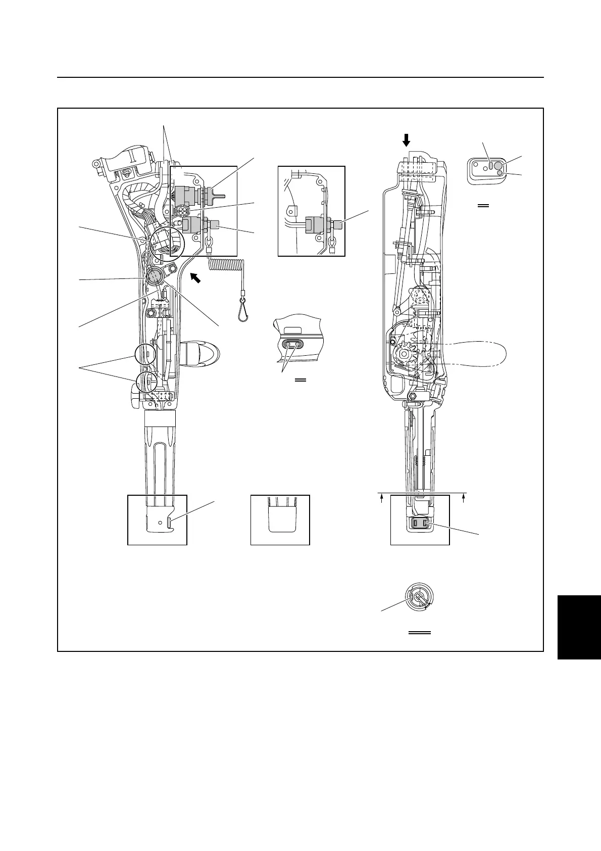
É Position the warning indicator coupler between
the engine start switch and the engine shut-off
switch, making sure that it is vertical. (E and W
model)
Ê Bend the 10-pin main harness as shown in the
illustration, and then connect the harness
coupler. The bend should be 10 mm (0.39 in)
or more from the coupler and have a bend
radius of 10 mm (0.39 in) or more. (E and W
model)
Ë Route the PTT switch lead above the warning
buzzer as shown. (PTT model)
Ì Route the neutral switch lead below the
warning buzzer as shown. (E and W model)
Í Fasten the PTT switch lead with the holder.
(PTT model)
Î Be careful not to pinch the PTT switch lead
between the steering handle and the bushing.
(PTT model)
S67C8008
B-B
A
C
È
Ë
Ì
3
8
5
É
6
7
2
2
1
BB
Í
Ê
Î
A
C
--
,
+
.
4
4
Electrical component and wiring harness routing