Chapter 3 PERFORMING MEASUREMENTS
3-83
2. Set marker Y1.
2-1. Locate the cursor to the position where Y1 is to be set, by turning the
rotary knob.
For the position for marker Y1, refer to page 3-84.
2-2. Press [F5] (NEXT PAGE).
2-3. Press [F1] (Y1).
“Y1” will appear at the cursor position.
3. Set marker Y3.
3-1. Locate the cursor to the position where Y3 is to be set, by turning the
rotary knob.
For the position for marker Y3, refer to page 3-84.
3-2. Press [F2] (Y3).
Marker Y3 will appear at the cursor position.
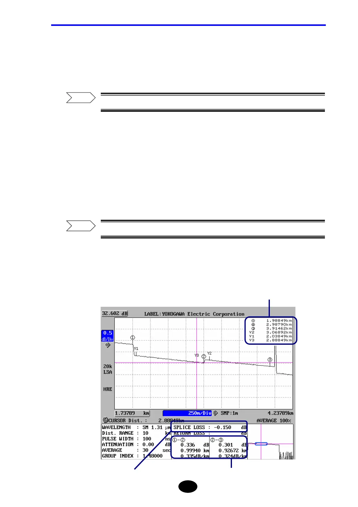
The splice loss will be displayed.
Splice loss
Distance from the origin to each marker
Inter-marker information
Refer
Refer
 Loading...


