Chapter 15 System Information
GS1920v2 Series User’s Guide
107
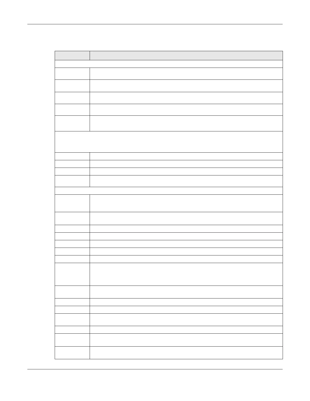
The following table describes the labels in this screen.
Table 26 MONITOR > System Information
LABEL DESCRIPTION
System Information
System
Name
This displays the descriptive name of the Switch for identification purposes.
Product
Model
This displays the product model of the Switch. Use this information when searching for firmware
upgrade or looking for other support information in the website.
ZyNOS F/W
Version
This displays the version number of the Switch 's current firmware including the date created.
Ethernet
Address
This refers to the Ethernet MAC (Media Access Control) address of the Switch.
CPU
Utilization
Current (%)
This displays the current percentage of CPU utilization.
Memory Utilization
Memory utilization shows how much DRAM memory is available and in use. It also displays the current percentage
of memory utilization.
Name This displays the name of the memory pool.
Total (byte) This displays the total number of bytes in this memory pool.
Used (byte) This displays the number of bytes being used in this memory pool.
Utilization
(%)
This displays the percentage (%) of memory being used in this memory pool.
Hardware Monitor
Temperature
Unit
The Switch has temperature sensors that are capable of detecting and reporting if the
temperature rises above the threshold. You may choose the temperature unit (Centigrade or
Fahrenheit) in this field.
Temperature
(C/F)
BOARD / MAC and PHY/POWER refers to the location of the temperature sensor on the Switch
printed circuit board.
Status This field displays Normal for temperatures below the threshold and Error for those above.
Current This shows the current temperature at this sensor.
MAX This field displays the maximum temperature measured at this sensor.
MIN This field displays the minimum temperature measured at this sensor.
Threshold This field displays the upper temperature limit at this sensor.
Fan Speed
(RPM)
A properly functioning fan is an essential component (along with a sufficiently ventilated, cool
operating environment) in order for the device to stay within the temperature threshold. Each
fan has a sensor that is capable of detecting and reporting if the fan speed falls below the
threshold shown.
Status Normal indicates that this fan is functioning above the minimum speed. Error indicates that this
fan is functioning below the minimum speed.
Current This field displays this fan's current speed in Revolutions Per Minute (RPM).
MAX This field displays this fan's maximum speed measured in Revolutions Per Minute (RPM).
MIN This field displays this fan's minimum speed measured in Revolutions Per Minute (RPM). "<41" is
displayed for speeds too small to measure (under 2000 RPM).
Threshold This field displays the minimum speed at which a normal fan should work.
Voltage(V) The power supply for each voltage has a sensor that is capable of detecting and reporting if the
voltage falls out of the tolerance range.
Status Normal indicates that the voltage is within an acceptable operating range at this point;
otherwise Error is displayed.
 Loading...