Chapter 33 PoE Setup
GS1920v2 Series User’s Guide
202
33.2 PoE Setup
Use this screen to set the PoE power management mode, priority levels, power-up mode and the
maximum amount of power for the connected PDs.
Click the PoE Setup tab in the PORT > PoE Setup screen. The following screen opens.
Consuming
Power (W)
This field displays the amount of power the Switch is currently supplying to the connected PoE-
enabled devices.
Allocated Power
(W)
This field displays the total amount of power the Switch (in classification mode) has reserved for
PoE after negotiating with the connected PoE devices. It shows NA when the Switch is in
consumption mode.
Consuming Power (W) can be less than or equal but not more than the Allocated Power (W).
Remaining
Power (W)
This field displays the amount of power the Switch can still provide for PoE.
Port This is the port index number.
State This field shows which ports can receive power from the Switch.
• Disable – The PD connected to this port cannot get power supply.
• Enable – The PD connected to this port can receive power.
Class This shows the power classification of the PD. Each PD has a specified maximum power that fall
under one of the classes.
The Class is a number from 0 to 4, where each value represents the range of power that the
Switch provides to the PD.
Each class corresponds to a default maximum power that can be extended in Basic Setting >
PoE Setup > PoE Setup to the following values.
• Class 0 – default: 0.44 W to 15.4 W, can be extended to 17.8 W.
• Class 1 – default: 0.44 W to 4 W, can be extended to 5.8 W.
• Class 2 – default: 0.44 W to 7 W, can be extended to 9 W.
• Class 3 – default: 0.44 W to 15.4 W, can be extended to 17.8 W.
• Class 4 – default: 0.44 W to 30 W, can be extended to 32.8 W.
Priority When the total power requested by the PDs exceeds the total PoE power budget on the Switch,
you can set the priority to allow the Switch to provide power to ports with higher priority first.
• Critical has the highest priority.
• High has the Switch assign power to the port after all critical priority ports are served.
• Low has the Switch assign power to the port after all critical and high priority ports are
served.
Power-Up This field displays the PoE standard the Switch uses to provide power on this port.
Consuming
Power (W)
This field displays the current amount of power consumed by the PD from the Switch on this port.
Max Power (W) This field displays the maximum amount of power the PD could use from the Switch on this port.
This field displays “–” if the maximum power is not specified in PORT > PoE Setup > PoE Setup.
Time-Range
State
This field shows whether or not the port currently receives power from the Switch according to its
schedule.
• It shows “
In” followed by the time range name if PoE is currently enabled on the port.
• It shows “Out” if PoE is currently disabled on the port.
• It shows “–” if no schedule is applied to the port. PoE is enabled by default.
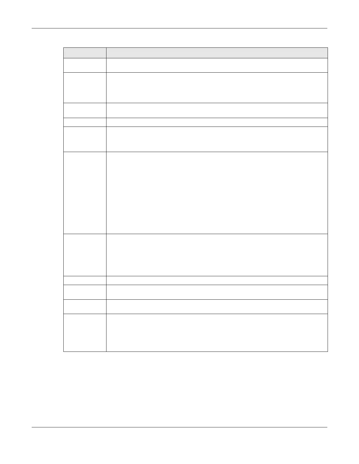
Table 96 PORT > PoE Setup > PoE Status (continued)
LABEL DESCRIPTION
 Loading...