Demonstration program | Programming
9
Programming a tool for turning a contour
The next feature to be turned is the contour near the center of the
part. For this, a tool change is necessary. Use a tool with a neutral
orientation (2).
Press the TOOL key to access the Set Tool dialogue
Press the Tool Table soft key to open the Tool Table
Select or define the appropriate tool with an orientation of 2
Press the USE key
The tool number and its dimensions and offsets will be
displayed in the Set Tool dialogue
Select Forward in the Spindle field
Enter 500 in the Speed field
Enter 2.00 in the Tool Position:X field
Enter 3.00 in the Tool Position:Z field
Press the USE key
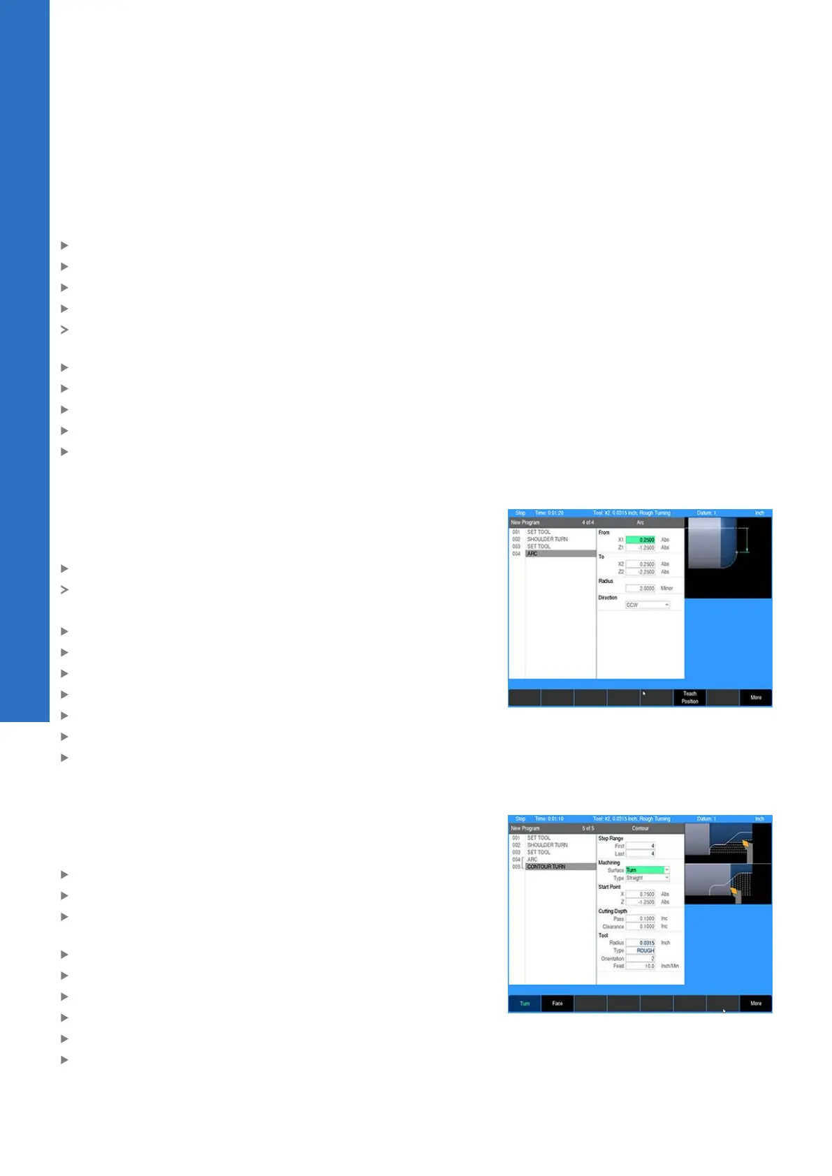
Programming a contour’s profile
A contour’s profile is defined by one or more connected lines, arcs,
blends, or chamfers. For this example, the contour consists of a
single arc.
Press the ARC key
The cursor will default to the From:X1 field in the ARC dialogue
Use the numeric keypad to enter the following information:
In the From:X1 field enter 0.25
In the From:Z1 field enter -1.25
In the To:X2 field enter 0.25
In the To:Z2 field enter -2.25
Enter 2 in the Radius field
Select CCW in the Direction field
Press the USE key
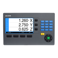
Programming a contour step
Although this is a simple profile which could be run as a single
arc step, we will program a contour step to show some of its
capabilities.
Press the TURN key
Select Contour from the popup menu
Press the Turn soft key for longitudinal machining along the
rotary axis
Select the appropriate tool path Type
Enter 0.75 for Start Point:X
Enter -1.25 for Start Point:Z
Enter 0.1 for the Cutting Depth:Pass
Enter 0.1 for the Cutting Depth:Pass
Press the USE key
150
ACU-RITE | TURNPWR | User's Manual | 08/2020