Program edit mode | Programming introduction
5
View hard key
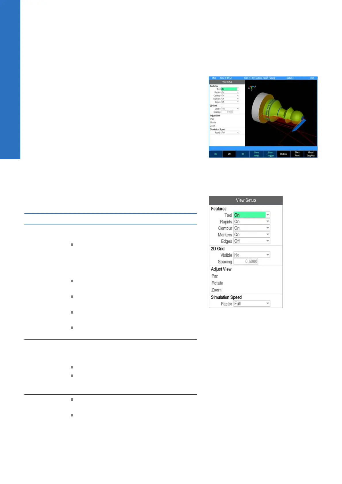
While in PGM mode or running a program, pressing the VIEW key
opens the View Setup dialogue. Several adjustment and graphical
display options can be set here. To save changes, press the VIEW
or USE key. Pressing the CANCEL key rejects the changes made
and restores the graphics view to the previous state.
For drop down menus, use the Right Arrow key to open, the Left
Arrow key to close, and the Up Arrow or Down Arrow key to make
a menu selection from the list.
All settings, except Adjust View and Simulation Speed, will remain
until changed again. This also applies to system reboots and
software updates.
For proper simulation when Show Model is active, make sure
that tools are defined in the program. Each unique tool will be
assigned a different color which will be used to display the material
it removes so that it is clearly visible which tool removed which
areas of block material.
The following describes the View Setup dialogue soft keys and drop
down menu options available.
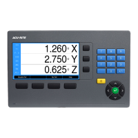
View setup
Features
Features can be turned on and off and are
graphical representations of the following:
Tool is the solid tool component, which
represents the tool as it moves, and changes
between the color blue when it is outside
of the material and red while it is actively
cutting material
Rapids are the tool movements that are set
at a rapid feed rate
Contour is the geometry of the
programmed contour
Markers are the zero point marker and
reference point markers
Edges are the blockform edge lines which
outline the material in the X, and Z axes
2D Grid
In 2D views, an overlay grid can be used in
conjunction with the edge ruler to aid with
visual measurements within the graphic display.
Visible allows the grid to be turned on or off
Spacing adjusts the amount of distance
between the grid lines, and is relative to the
actual part size
Adjust View
These three buttons allow you to adjust the
graphic display.
Cursor to the appropriate button: Pan,
Rotate, or Zoom then press the ENTER
key to activate the adjustment mode. The
button text will shift to the right side of the
button to indicate that the adjustment mode
68
ACU-RITE | TURNPWR | User's Manual | 08/2020