Machining fundamentals | Tool dimensions
3
3.3 Tool dimensions
The control requires information on the specific tools for a variety
of tasks, such as positioning the axes, calculating the cutting radius
compensation or the proportioning of cuts.
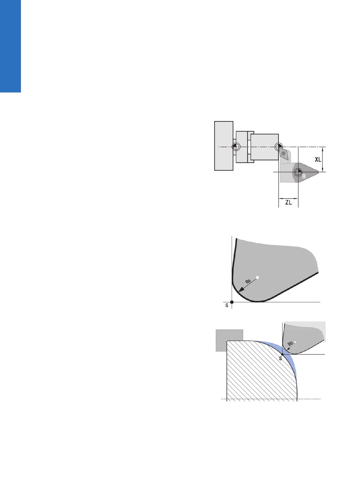
Tool length
All programmed and displayed position values are given with
respect to the distance between the tool tip and workpiece datum.
Since the control only knows the absolute position of the tool
carrier (slide), it needs the dimensions XL and ZL to calculate and
display the position of the tool tip.
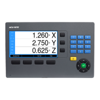
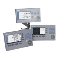
Tool-tip radius compensation (TRC)
The tip of a lathe tool has a certain radius. When machining tapers,
chamfers and radii, this results in inaccuracies which the control
compensates with its cutting radius compensation function.
Programmed paths of traverse are referenced to the theoretical
tool tip S. With non-paraxial contours, this will lead to inaccuracies
during machining.
The TRC function compensates for this error by calculating a new
path of traverse, the equidistant line.
42
ACU-RITE | TURNPWR | User's Manual | 08/2020