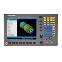
Setup | Job setup
11.2 Job setup
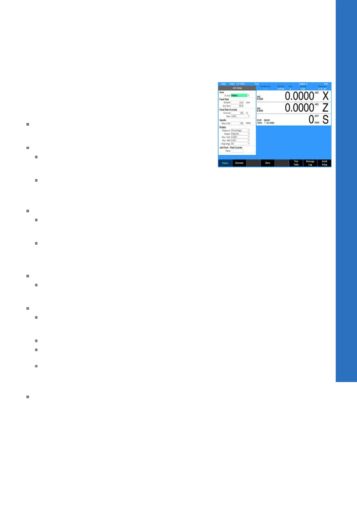
The Job Setup dialogue is displayed by default when the SETUP
key is selected.
In the Job Setup dialogue there are parameters that can be set
which the control will default to when not overridden by another
setting.
X Axis: The mode of the system can be set to either Radius
(default) or Diameter mode. All programming input and position
display for the X Axis will adhere to the mode selected here.
Feed Rate:
The Default setting is the setting that the control will use as
the default in a program unless it is defined explicitly by a
step that is in the program.
The Dry Run feed rate specifies the feed rate to be used
when running a program in Dry Run mode with no coolant
or spindle motion. For additional information see "Dry run",
Page 102.
Feed Rate Override:
The Full Cut field override percentage is applied to a step's
programmed feed rate when the tool makes cuts greater
than the programmed step over percentage
The Max field determines the feed potentiometers maximum
override percentage. The acceptable range is 150% to
200%. The last click of the dial will allow the Max setting.
The second to the last click will always be 140%.
Spindle:
The Max CSS RPM specifies the maximum RPM to allow the
spindle to operate at when in Constant Surface Speed mode
(equivalent to G50 in ISO programming)
Display:
Stepover: This defines the step over amount for machining
operations as either a percentage of the tool’s width or as a
distance
Angles: The setting can either be in Degrees or DMS
Res. Inch and Res. MM: Select the desired display resolution
for the DRO display.
Help Imgs: The setting can either be set to On to always
show the field graphic assistant in a step form. Or set to
Automatic for displaying additional fields when available in
place of the graphic assistant.
Job Clock - Parts Counter: For setting the parts counter and
stopping or starting the Job Clock. The Job Clock will provide an
estimate of time to machine the part and overall Job time, see
"Job clock", Page 177.
X Axis
This setting defines the active mode of the system for the X Axis,
either Radius or Diameter. All programming input data and position
display for the X Axis will follow this mode setting. When set to
Diameter, the DRO and status bar will indicate this by displaying a
Ø symbol.
11
ACU-RITE | TURNPWR | User's Manual | 08/2020
175