1100 Series Nano Pump Service Manual 197
Introduction to the Nano Pump 5
How Does the Pumping unit Work?
Both pumping units (channel A and channel B) are identical with respect to
parts and function. Each pumping unit consists of a pump head which is
directly attached to a metering drive assembly.
In each metering drive assembly, a servo-controlled variable reluctance motor
and gear train assembly are used to move two ball-screw drives. The gear train
moves the two ball-screw drives in opposite directions (180 degree out of
phase). The gear ratios are designed such that the first ball-screw drive
constantly moves at twice the speed of the second ball-screw drive. The servo
motor includes a high resolution shaft-position encoder, which continuously
reports the speed and direction of the motor in real time. This speed and
direction information is used by the pump control electronics to ensure
precise control of the servo motor movement.
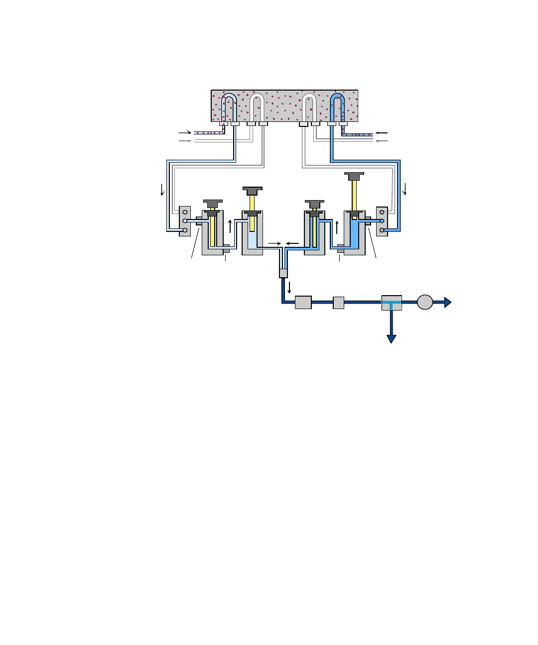
Figure 38 The Hydraulic Path
To waste
Damper
Outlet
valve
Inlet
valve
Outlet
valve
Mixing
chamber
From
solvent
bottle
Piston
Seal
Pump head BPump head A
Filter
EMPV Flow sensor
From
solvent
bottle
Inlet
valve
Degasser
 Loading...


