6.3 Tuning fuel 6 TUNING THE MS3PRO
We’ll cover measuring injector dead time in more detail in the Advanced section.
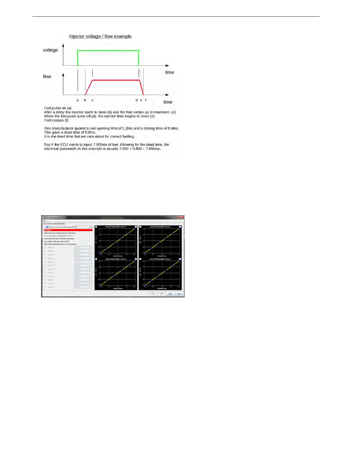
6.3.2 Small pulse widths
At most pulsewidths (say above 2ms), injectors behave in a linear manner, where 10% increase in effective
pulsewidth gives a 10% increase in fuel flow. The MS3Pro normally relies on this linear behavior for fuel cal-
culations. However, at small pulsewidths, injectors behave non-linearly. This table allows for you to correct for this.
You may specify up to four separate curves if you determine that your injectors do not all work the same.
The Injector Small Pulsewidths feature allows the user to make a correction and make the non-linear region
more linear in nature. Unless you have calibration data for your injectors measured on your MS3Pro, this feature
should be left turned off. The X-axis of the curve is the MS3Pro pulsewidth (before deadtime is applied) and the
Y-axis is the required injector pulsewidth (before deadtime) that the injector needs to approximate linearity. Most
injectors observed exhibit an "S" shaped non-linear region. Nothing happens for the first few 0.1ms after dead time,
so a curve that effectively adds on PW to the very low values will help linearize this somewhat. The non-linear
region also frequently shows a "lump" which will make linearization tricky. See the dead time measurement section
for real measured data.
Here are some example curves based on data from real injectors. Note that no allowance is made for the
"lump" which will distort the results. The injectors were linear by 1.2ms (plus dead time) so the curve is arranged
from 0-1.2ms.
AMP EFI MS3Pro manual version 1.202, firmware 1.5.0, 4/21/2017 Page 110