7.10 CAN bus / Testmodes 7 ADDITIONAL ITEMS: BEYOND BASIC FUEL AND IGNITION CONTROL
7.10.11 Check Engine Light
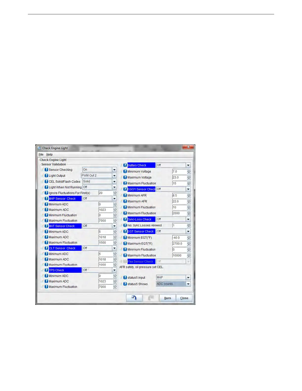
The MS3Pro has a sensor validation system that can sanity check the sensor inputs. If the sensor appears to be
malfunctioning, then it can switch on a Check Engine light. Additionally, limited operating strategies (limp modes)
can be enabled. The aim of these settings is firstly to warn you of a failed sensor that could cause poor or
damaging engine operation and secondly, through the limp modes, to allow some engine operation even with the
failed sensor. The checking scheme varies slightly for each sensor. Most sensors are checked against minimum
and maximum possible values that can occur if the wire breaks or is shorted to ground or 5V. The other criteria is
minimum and maximum fluctuation - this is to detect a stuck or wildly flailing sensor. All of these parameters are
engine specific, and you will need to dial them in for your installation.
The sensor validation often works with ADC counts. ADC stands for analog to digital converter, and refers to
a circuit in the MS3Pro’s processor that converts an analog voltage to a digital readout. The MS3Pro converts
sensor readings into a 0 to 5 volt signal that goes to the processor, and the processor uses a 10 bit converter to
turn this into a value that ranges from 0 at 0 voltage to 1023 at 5 volts. Usually, these ADC counts are hidden from
the user - you’re more interested in what the sensor reading actually means than a raw number. However, with
sensor diagnostics, you’ll be looking at the ADC count directly, since we’re looking at establishing when a signal
doesn’t mean anything other than that your sensor isn’t working. For starting settings, try a minimum ADC value
of 5, and a maximum ADC value of 1018. You can use Status 5 to data log the actual ADC readings.
The fluctuation units are a bit arbitrary; we recommend data logging the values to see what is normal, and
using that to set the minimum and maximum values.
• Sensor checking - Enables or disables this system
• Light output - Selects an optional output for the Check Engine Light. Recommended. Note that this can
share a channel with the AFR Safety warning light.
• CEL Solid / Flash Codes - You can have the Check Engine light stay on, or transmit flash codes.
• Light When Not Running - Specify if the Check Engine light should be off or on when the engine RPM is at
zero.
AMP EFI MS3Pro manual version 1.202, firmware 1.5.0, 4/21/2017 Page 267