5.3 Ignition settings 5 SETTING UP A BASIC CONFIGURATION
Trigger angle range Notes
Negative Not allowed. Will create error message on power up.
0 - 15 Allowed. Timing cannot be retarded to less than trigger angle. Best
cranking timing.
15-49 Not allowed. Engine will not be able to run on full timing range.
50-59 Allowed, but not ideal. Will not allow advance numbers past ~48
degrees.
60-90 Allowed. Provides best accuracy at high RPM and allows ATDC
timing retard.
91-120 Allowed on engines with 6 cylinders or fewer. Not recommended,
hard starting.
121-180 Allowed on engines with 4 cylinders or fewer. Not recommended, may
be impossible to start.
For best accuracy at high revs or during transients, aim for the trigger to align at 60-90° BTDC. This also allows
a full range of timing and including retarded timing should you need it for boosted conditions. This range of trigger
angle is preferred for new installs. For slightly better starting, but not quite such good running accuracy, aim for
a trigger ~10° BTDC or your desired cranking advance. This is the typical trigger angle for TFI and computer
controlled HEI. You cannot retard timing later than the trigger angle. e.g. 9° BTDC and lower are not possible with
a 10° BTDC trigger angle.
The VR sensor input presents a simple pulse as the reluctor passes the sensor, this gives a timing position
easily identified by eye. Rotate the engine to 60° BTDC (or 10° BTDC if chosen) and then align the distributor so
the reluctor aligns with the center of the sensor.
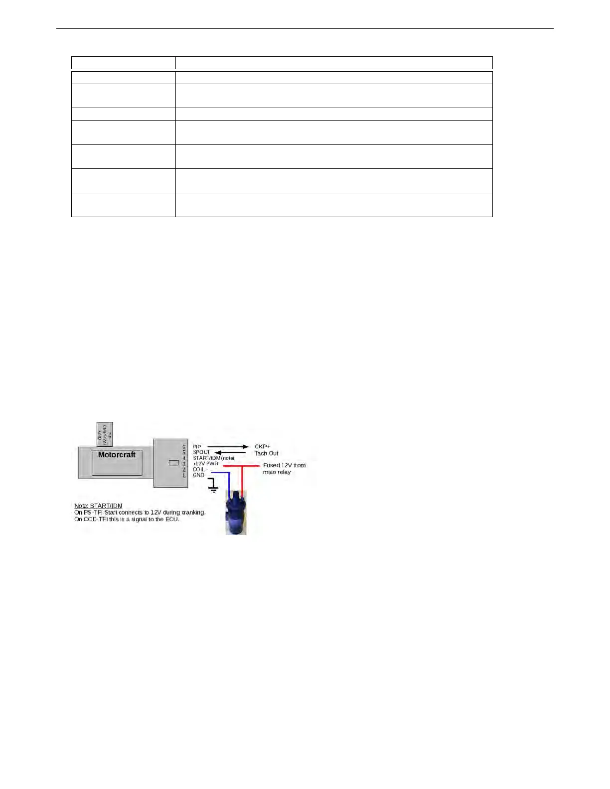
5.3.1.2 Ford TFI distributors Ford’s TFI module was used throughout the 1980s and into the 1990s on many
millions of vehicles in two main mounting positions - “distributor mount” and “remote mount”. There are also
two electrical versions: "Push Start" and "Computer Controlled Dwell" : documentation claims that these can be
distinguished by color, but that appears unreliable. Checking the wiring on pin4 is likely best. The wiring of the
modules is largely the same, just the distributor mount connects directly to a 3 wire hall sensor in the distributor. In
most installations you do not need to concern yourself with that as only the “PIP” and “SPOUT” connections are of
interest. The other connections should be left stock.
The white wire on the CKP input connects to the PIP signal, and the Tach Out wire (NOT Spark A Out) connects
to PIP. Be sure “Spark hardware in use” is set to Tacho.
The module described mainly here is the "Push Start" type that uses a 12V start signal. While some documen-
tation claims that all “PS” type modules are gray, we’ve seen them in black as well. A more reliable indicator is that
pin 4 will be connected to a 12 volt source when cranking. 50% dwell duty should be used. On the "CCD" type,
pin 4 runs as a diagnostic signal to the original ECU. These modules need normal dwell control instead of a fixed
duty. We recommend starting with 3.0 ms dwell and adjusting to match the coil used. Other wiring should be the
same.
"Base Timing" on the distributor (with computer control "SPOUT" disconnected) is around 10BTDC. This is the
number you should use as your initial Trigger Offset, and adjust as needed to obtain correct timing. As these
distributors were designed for ECU control, the rotor arm phasing should already be correct.
The “Signature PIP” versions of the TFI distributor have a shorter vane used to identify the #1 cylinder. These
appeared on factory sequential injected engines. These are still set up as basic trigger, but you will set “TFI
Signature PIP” under Ford TFI Options.
Set “Ignition Input Capture” to “Falling Edge” and Spark Output to “Going High”.
AMP EFI MS3Pro manual version 1.202, firmware 1.5.0, 4/21/2017 Page 61