4.3 Engine position sensors 4 WIRING
4.3 Engine position sensors
The MS3’s CKP ((crankshaft position) and CMP (camshaft position) inputs use differential signal conditioners that
can accept input from VR (variable reluctor, also called a inductive pick-up or magnetic pick-up, although the latter
is somewhat confusing because Hall effect sensors are also magnetic), Hall effect, or optical sensors. We use
CKP to mean the primary trigger. In most spark modes, this is the signal the ECU relies on for most of its RPM
and timing calculations. Although the abbreviation implies the sensor should be on the crankshaft, in some cases,
it’s actually in a distributor or on the camshaft.
The CMP signal is a secondary trigger. This is almost always on the camshaft or distributor, although there are
one or two setups that put this on the crank. The CMP sensor generally provides supplemental information used
to interpret the crank sensor readings, and its accuracy is usually not as critical. Here are the rules we go by to
identify which sensor is the CKP and which is the CMP.
• If one sensor spins at crankshaft speed and the other spins at cam speed, the one that turns at crank speed
is the CKP and the one at cam speed is the CMP.
• On a GM Optispark and most Nissan optical cam sensors, the MS3Pro normally uses a ring with one slot per
cylinder for primary engine operation. There is a ring of 360 slits that is used for cranking and operation at
very low RPM. Consequently, the one slot per cylinder sensor is the CKP and the 360 slot ring is CMP. (Note
that these use Digital Frequency In 2 for the CMP sensor, as the regular CMP input is too heavily filtered to
correctly handle this signal.)
• On almost all other setups with two sensors reading wheels spinning at cam speed, the sensor that reads
the wheel with the lowest number of teeth is CMP and the one with the most teeth is CKP.
• Specific sensor setups that do not fall into any of these categories are covered in the ignition set-up section
of the manual.
Note that the conditioner circuit will invert the signal. We have left the settings unchanged for backward compability
with the original MegaSquirt line. So if you set the ignition input capture to “rising edge”, that is the signal at the
processor - it will actually be activated when the signal coming in to the MS3Pro transitions from high to low.
4.3.1 Variable reluctor sensors
Variable reluctor (VR) sensors have a magnet and a coil of wire which generates an A/C signal with a voltage that
increases with RPM. VR sensors do not have power wires as they generate their own voltage. On a VR sensor,
you will wire their two terminals to both of the CKP or CMP wires, as appropriate. Don’t worry too much about
getting it backwards - you can set the active edge in software.
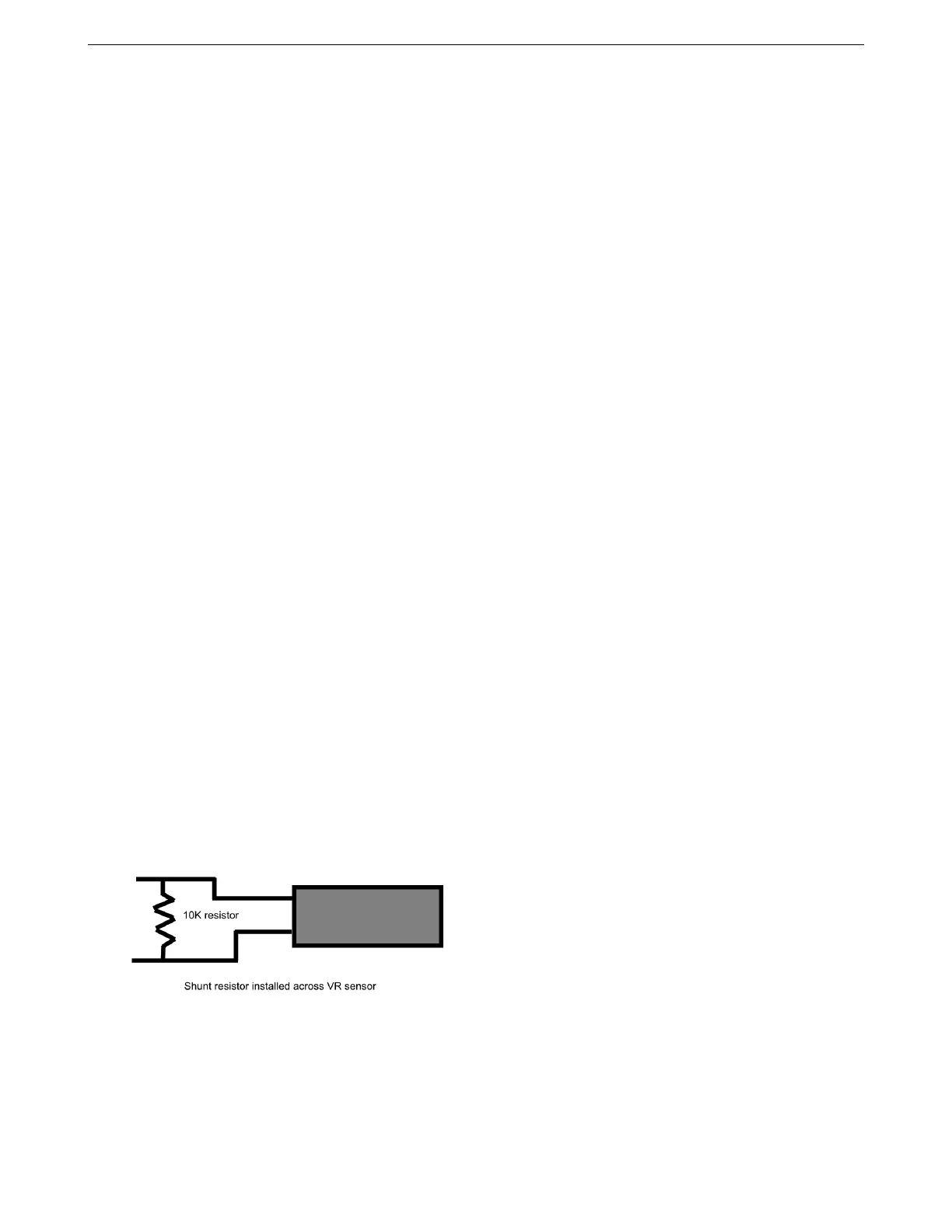
The MS3Pro package includes two 10K resistors sealed in red sealed tubing with yellow wire leads. If you are
using a VR sensor on a high tooth count wheel with missing teeth (Ford 36-1 and Bosch 60-2 are two common
examples) and lose sync as the RPM comes up, install one of the 10K resistors in parallel with the sensor. This
fixes the problem in most cases.
4.3.2 Hall effect and optical sensors
Hall effect and optical sensors work on different principles of physics, but these two types of sensors use the same
wiring. These use a switching transistor and are powered from an external source (either 5 or 12 volts; if your
sensor can run on either, we recommend using 12 volts). Your typical sensor has three pins - the power wire goes
to a 12 or 5 volt feed, the ground wire goes to sensor ground, and the signal wire goes to CKP+ or CMP+ as
AMP EFI MS3Pro manual version 1.202, firmware 1.5.0, 4/21/2017 Page 36