4.4 Other sensors 4 WIRING
4.4.2 MAP sensors
Most MS3Pro installations use a MAP sensor for load measurement. The original MS3Pro is designed to use an
external MAP sensor only.
The MS3Pro supports both frequency and voltage based MAP sensors. We recommend GM MAP sensors if
using an external MAP sensor, which are voltage based, because they are inexpensive and readily available in
several different maximum pressures. Be sure to select a MAP sensor that can read as much pressure as you
intend to run. On turbo cars, we recommend giving a slight amount of extra room to allow the ECU to detect if the
boost control has malfunctioned.
MAP sensor type Maximum boost level
1 bar naturally aspirated
2 bar 14 psi
3 bar 29 psi
4 bar 44 psi
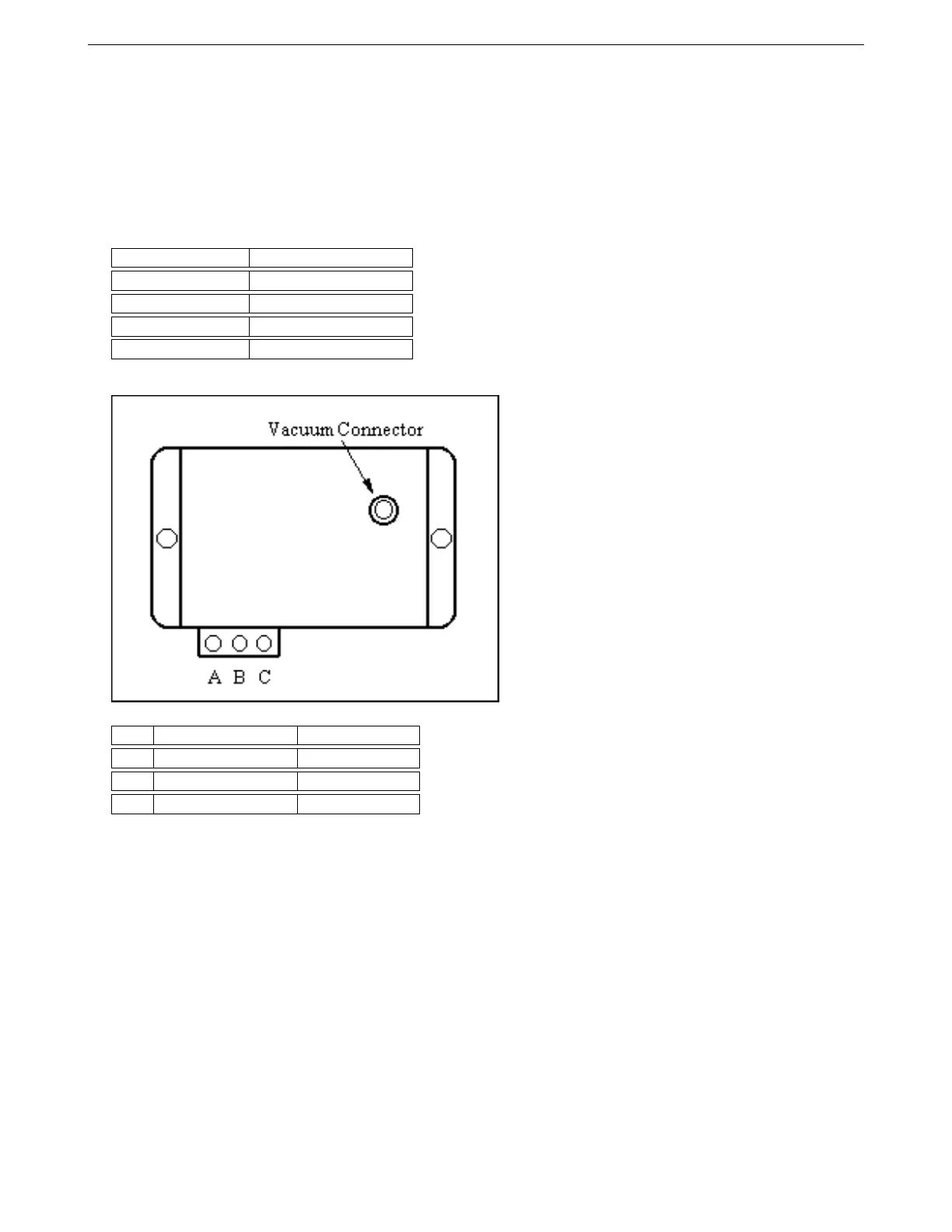
Install the MAP sensor with the hose fitting pointed downward, or at most, 30 degrees from vertical. This will
prevent oil or blow-by from accumulating in the sensor, which can damage its circuitry.
Here are what the pins on the GM MAP sensor do:
Pin Function Connection
A Ground Sensor return
B Sensor output MAP in
C Reference voltage 5V+ VREF Out
MAP sensors will have three pins unless they have some sort of additional sensor (usually a temperature
sensor) in the same package. The reference voltage connects to the MS3Pro’s VREF pin, and the ground pin
to the sensor ground wire. For a voltage based MAP sensor, connect the signal pin to the MS3Pro’s MAP input
wire. An additional MAP sensor may be used to measure barometric pressure on one of the spare analog inputs.
Frequency based MAP sensors such as those used in Ford Mustangs must be wired to a Digital Frequency In wire
instead of the MAP or analog inputs. (You can also use the CMP+ wire for a frequency based MAP sensor, if you
are not using it for cam position.)
4.4.3 Throttle position sensor
The throttle position sensors used on most cars are potentiometer or variable resistance types, which put out a
voltage that increases as the throttle opens. The easiest way to check a TPS is to unplug it and put an ohmmeter
on its pins. Observe the resistance as the throttle opens and closes. Each pair of pins will behave differently:
The resistance between the VREF and ground pins will remain constant. The resistance between the ground
and signal pins will be low with the throttle closed and high with the throttle wide open. The resistance between
the VREF and signal pins will be high with the throttle closed and low with the throttle wide open.
If your sensor behaves like this, it will be pretty straightforward to connect it to the MS3Pro.
AMP EFI MS3Pro manual version 1.202, firmware 1.5.0, 4/21/2017 Page 38