7.3 Ignition Settings 7 ADDITIONAL ITEMS: BEYOND BASIC FUEL AND IGNITION CONTROL
• Inj D Secondary injector A
• Inj E Secondary injector B
• Inj F Secondary injector C
The coils and injectors need to be wired in firing-order sequence. The outputs fire A,B,C,D,A....
7.3.11.5 4 rotor As with 3 rotor mode, this requires enabling coil on plug ignition.
Ignition wiring:
• Spark A Leading coil A
• Spark B Leading coil B
• Spark C Leading coil C
• Spark D Leading coil D
• Spark E Trailing coil A
• Spark F Trailing coil B
• Spark G Trailing coil C
• Spark H Trailing coil D
Fuel wiring:
• Inj A Primary injector A
• Inj B Primary injector B
• Inj C Primary injector C
• Inj D Primary injector D
• Inj E Secondary injector A
• Inj F Secondary injector B
• Inj G Secondary injector C
• Inj H Secondary injector D
The coils and injectors need to be wired in firing-order sequence. The outputs fire A,B,C,D,A....
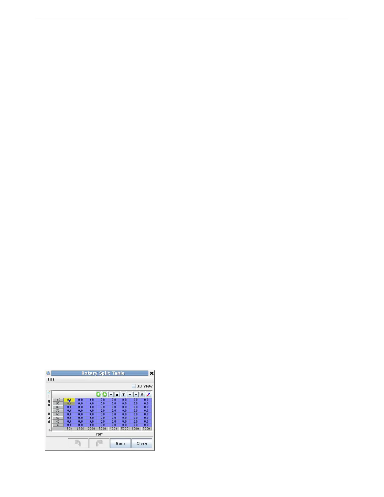
7.3.12 Rotary split table
This allows you to specify the split in degrees between leading and trailing sparks. Positive numbers mean the
trailing is later. Negative means that trailing is fired before leading.
AMP EFI MS3Pro manual version 1.202, firmware 1.5.0, 4/21/2017 Page 178