4.4 Other sensors 4 WIRING
If the resistance jumps from infinite (or near infinite) to near zero, you have a switch type throttle position sensor,
or possibly a seriously defective potentiometer type TPS. These do not provide very much information that MS3Pro
needs, as it can tell if you are at idle or full throttle by the MAP sensor information. You can still use MAP based
acceleration enrichment. If the TPS input is not used, this wire should be connected to sensor ground.
4.4.4 Mass air flow sensors
Mass air flow (MAF) sensors provide a measurement of actual airflow through the intake system of an engine. In
its most basic form, the fuel required by the engine (in mass per second) is directly related to the air flowing into the
engine (in mass per second) so the MAF sensor should give a good basis for the fuel equation. By comparison,
Speed Density uses RPM, MAP, MAT and VE to estimate the mass air flow. In practice, like any other sensor input
the MAF has its own quirks and can suffer from reversion effects (particularly on "cammy" engines) where the air
flow gets measured twice.
MAF sensors have at least three wires: Ground, power supply, signal.
• The power supply is typically 12V and should be taken from a fused source from the main relay.
• Signal GND should connect to MS3Pro sensor ground. If the sensor has only one ground, it’s sensor ground.
• If the sensor uses a terminal called Power GND, this should connect to the same point as the MS3Pro power
grounds.
• With a voltage MAF, you may use the MAP signal wire or any of the extra analog input wires.
• With a frequency based MAF, you may use any of the Digital Frequency In inputs, or the CMP+ wire if you
are not using it for cam position.
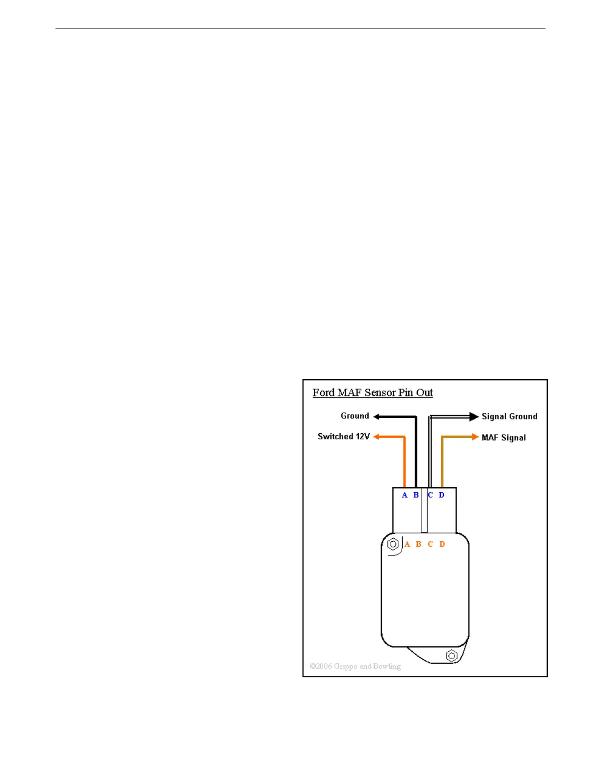
Here are some of the more commonly seen MAF pinouts.
4.4.4.1 Ford 5.0 Mustang 4 pin oval connector MAF
AMP EFI MS3Pro manual version 1.202, firmware 1.5.0, 4/21/2017 Page 39