7.3 Ignition Settings 7 ADDITIONAL ITEMS: BEYOND BASIC FUEL AND IGNITION CONTROL
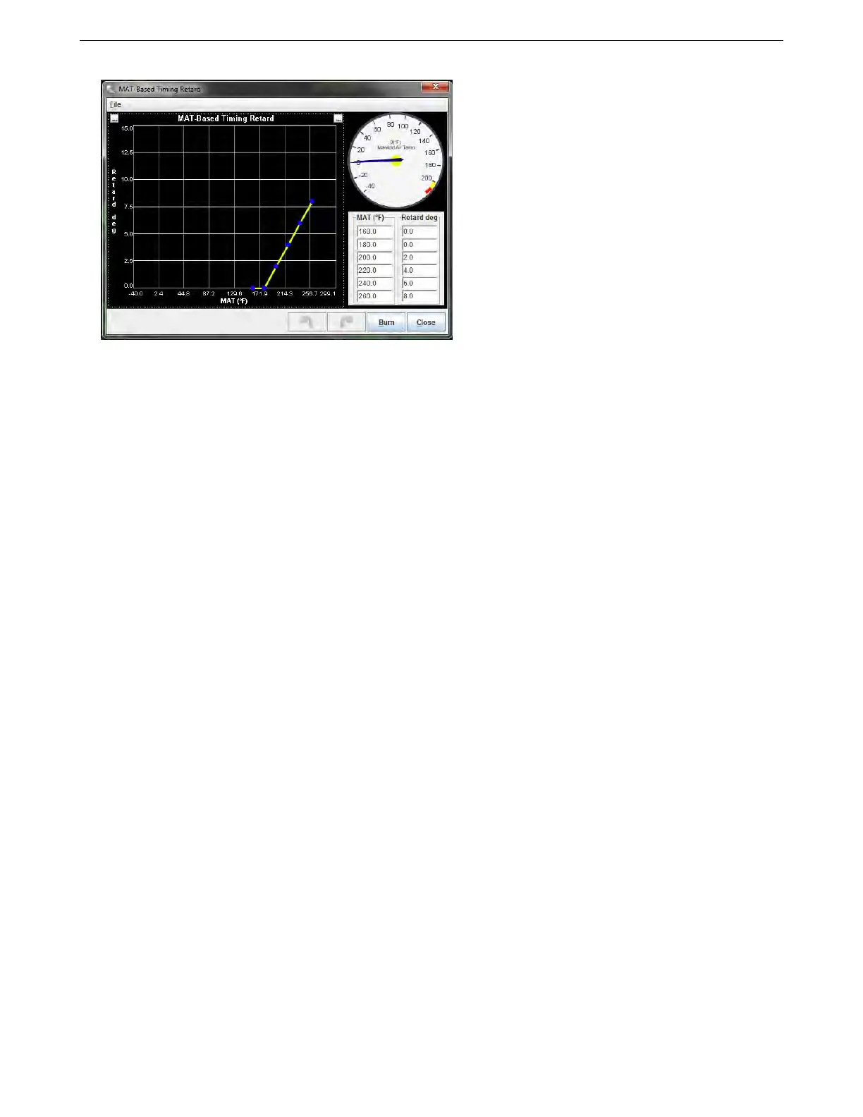
Ensure that the retard figure at normal temperatures is zero; this will allow the spark timing to follow the advance
table during normal operation.
7.3.6 Noise filtering
The noise filtering menu allows the MS3Pro to detect and ignore pulses on the crank and cam position inputs
caused by electrical noise.
In the simplest form of a fuel-only controller with a tach signal from the coil negative, the "ringing" of the coil
may cause apparent rpm spikes. This will cause additional fuel to be injected on each of these noise pulses and
show up as a falsely high rpm. It will likely be irritating, but no major problems are likely.
On an install controlling ignition, it is a different matter. In the simple distributor install with a simple trigger
arrangement (1 pulse per ignition event like in a normal distributor), the noise will cause a misfire probably on that
one event. On a multi-toothed wheel, the noise is likely to cause a loss of sync with the wheel, and spark will be
lost for 360 or even 720 degrees of engine rotation before the re-synchronization occurs.
So, the tach input is critical to ECU operation, it is important to reduce or eliminate that noise. Hardware is your
first line of defense. Here are some tips on setting up hardware to keep out noise:
• Set the sensor gap to an appropriate level. Most sensors work with a gap about the thickness of a normal
business card.
• Use shielded wire, like in our standard wiring harness. Ground the shield at only one end - a shield grounded
at both ends can carry current, and induce noise in the signal.
• Route the signal wire away from any electrical noise sources, such as ignition coils, spark plug wires, and
the alternator or starter.
• Ensure that the MS3Pro has a clean ground to the engine block, cylinder head, or negative battery terminal.
• VR sensors need to be connected to the positive and negative signal wires. Hall effect or optical sensors
should be grounded to the MS3Pro sensor ground.
With the hardware well defended against noise, the second line of defense is to set up the ECU to read the
sensors correctly and reject noise. The first setting is the ignition input capture is correct, as covered in section 5.
For example, the VR signal below has one stable and one unstable edge. It needs to be set to triggering on Rising
Edge.
AMP EFI MS3Pro manual version 1.202, firmware 1.5.0, 4/21/2017 Page 167