4.2 Wiring diagram 4 WIRING
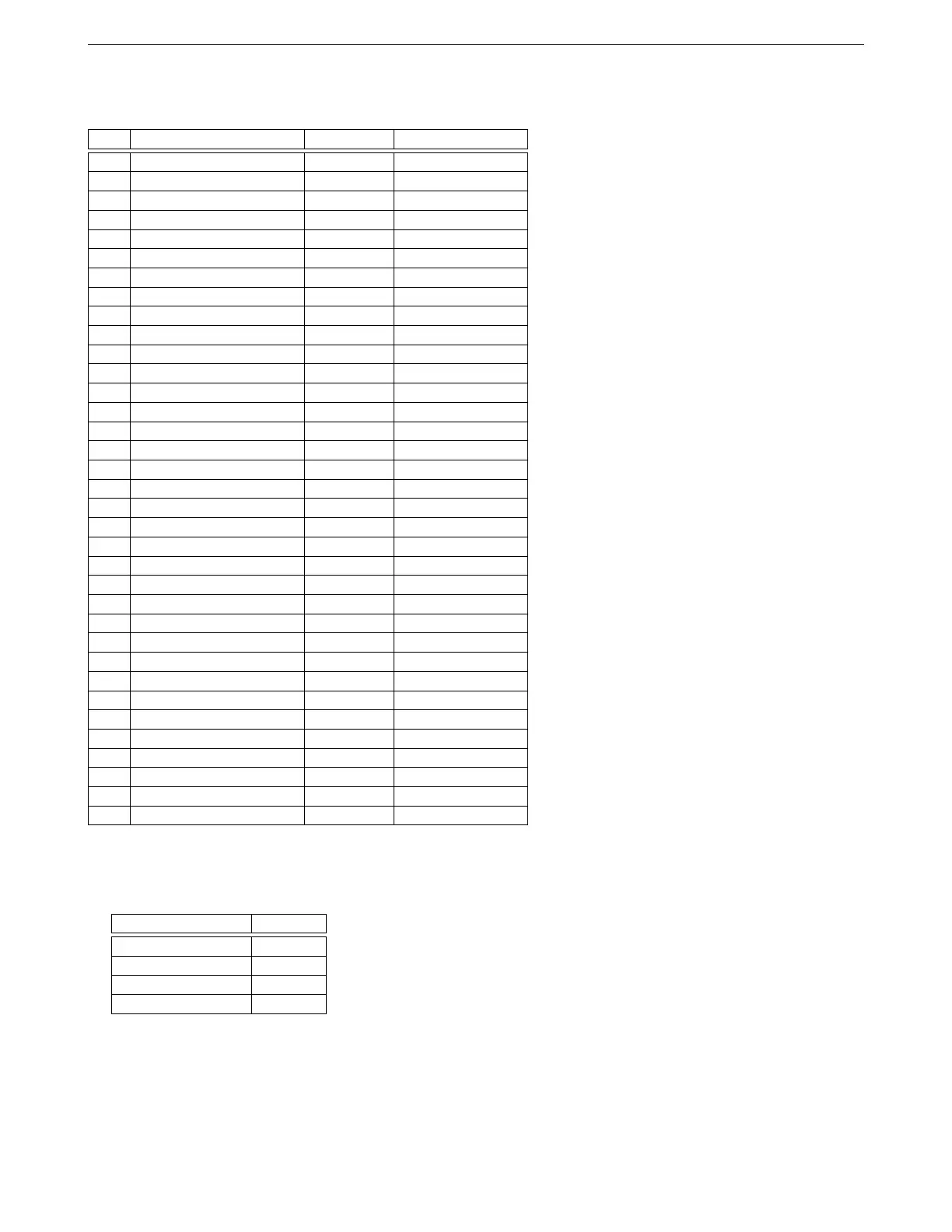
Gray connector pinout
Pin Function Wire color Stripe / shielding
1 Injector out A White None
2 Injector out B White Orange
3 Ground Black None
4 Injector out C White Light green
5 Ground Black None
6 Injector out D White Pink
7 Ground Black None
8 Injector out E White Red
9 Ground Black None
10 Injector out F White Dark green
11 Injector out G White Dark blue
12 Injector out H White Purple
13 Spark out G Yellow Dark blue
14 Spark out E Yellow Red
15 Spark out C Yellow Light green
16 Spark out H Yellow Purple
17 Digital frequency in 2 Purple Red
18 Ground Black None
19 Digital switched 12V in Gray Dark blue
20 Digital switched in 2 Gray Red
21 Digital frequency in 3 Purple Dark Blue
22 USB power Red USB shield
23 USB ground Black USB shield
24 Spark out F Yellow Dark green
25 Spark out B Yellow Orange
26 Spark out D Yellow Pink
27 Spark out A Yellow No stripe
28 Digital frequency in 1 Purple White
29 Digital switched in 3 Gray Purple
30 Stepper IAC out 1B Blue Red
31 Stepper IAC out 1A Blue White
32 Stepper IAC out 2A Green White
33 Stepper IAC out 2B Green Red
34 USB D- White USB shield
35 USB D+ Green USB shield
RS232 serial cable
The pin names are marked on the connector.
Weather Pack pin DB9 pin
A 5
B 9
C 2
D 3
4.2 Wiring diagram
These show the basic connections - power, ground, fuel, ignition, idle control, and basic sensors. Other optional
inputs and outputs are covered in their respective sections.
AMP EFI MS3Pro manual version 1.202, firmware 1.5.0, 4/21/2017 Page 32