7.1 Basic / Load Sections 7 ADDITIONAL ITEMS: BEYOND BASIC FUEL AND IGNITION CONTROL
• Alternator control duty - When control mode is set to open loop duty, this lets you specify what duty cycle
commands what charging voltage.
• Duty linearisation - When using closed loop field control, this curve translates what output percentage the
ECU has calculated (calc% on the X axis) into output duty cycle (output% on the Y axis). This allows you to
compensate for non-linear behavior or specify a minimum or maximum output duty cycle.
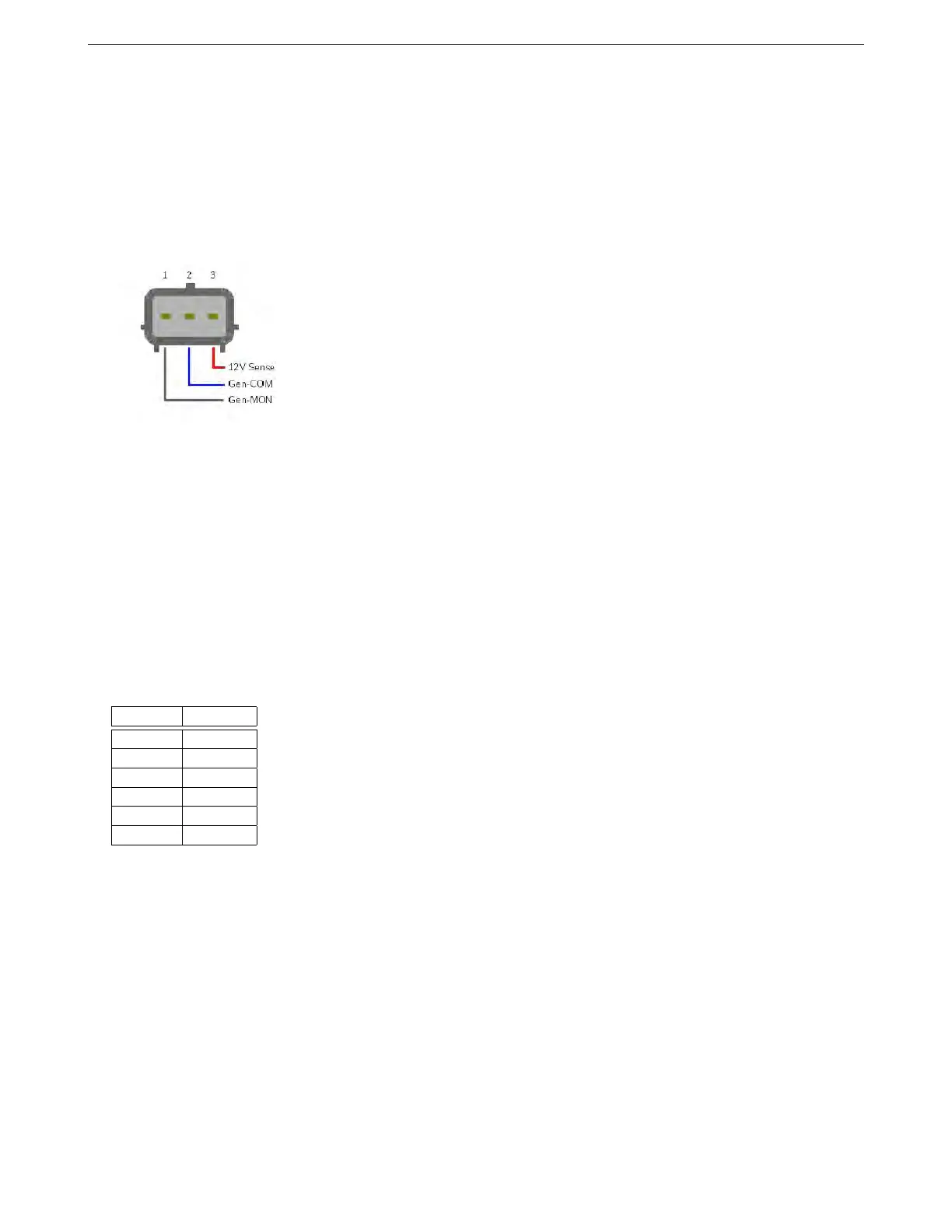
7.1.8.1 Ford alternators Ford added ECU controlled alternators starting in 1999. These use a three wire plug
as shown below.
• SENSE (or A or S) - this connects to battery voltage, typically near or at the battery.
• GEN-COM (or GEN RC or SIG or RC) - this is the ’command’ signal from the ECU to the alternator. Internally
the alternator pulls this to battery voltage through a 1K resistor. Connect to
• GEN-MON (or GFS or FR or LI) - this is the ’monitor’ signal from the alternator back to the ECU. The
alternator switches this to ground; it connects to a 0-5V frequency input on the ECU with a pullup resistor.
On the Ford Focus 98AB19399DF alternator tested, pin 3 (SENSE) was red, pin 2 (GEN-COM) was blue, and pin
1 (GEN-MON) was gray. Connect the GEN-COM to any unused high current or PWM output. Using the GEN-MON
wire is optional. If used, connect it to an unused digital frequency or switched input, and use a 1K pull up wire
between this input pin and VREF.
Ford uses a variable frequency system to set the alternator voltage. The 1.5.0 code allows setting a time period
instead of frequency, which allows setting a wider voltage range. Setting a frequency sets the target for the internal
voltage regulator. Turning off the signal or commanding a voltage of 12.0 V or lower will shut off alternator charging.
Voltage Period
12.0 V 0.5 ms
12.8 V 3.4 ms
13.6 V 6.3 ms
14.4 V 9.3 ms
15.2 V 12.2 ms
16.0 V 5.1 ms
These alternators use the following settings:
• Control mode: Open loop frequency
• Control output: Use any available high current or PWM output.
• Output polarity: Normal
• Load monitor input: Can be set to off or an available digital switched or frequency input.
• Capture polarity: If using load monitor input, set this to Inverted.
7.1.8.2 Chrysler alternators Chrysler alternators have used an external field controller on their alternators
since they started production of their own in-house alternators for the 1960 model year. Later Bosch and Nippon-
denso alternators used on their cars and trucks follow the same pattern of bringing out the field terminals for an
external device instead of using internal regulation. Chrysler eventually integrated the voltage regulator control
into the ECU, but did not change the alternator construction itself. The result is that you can control even 1960s
AMP EFI MS3Pro manual version 1.202, firmware 1.5.0, 4/21/2017 Page 135