7.6 Boost / VVT 7 ADDITIONAL ITEMS: BEYOND BASIC FUEL AND IGNITION CONTROL
• Tooth 2 - same again, but for second crank revolution.
• More duty means - whether more PWM duty on the solenoid causes the cam to advance or retard.
Note that on dual solenoid applications, such as the BMW S54 mode, the Cam 1 solenoid is used to advance
the main cam and the Cam 3 solenoid is used to retard the same cam. Cam 2 advances the secondary (usually
exhaust) cam, while Cam 4 retards this cam.
The most basic setup is to make the wiring connections for inputs and outputs. Most engines will run safely
with VVT inactive; ensure this is the case on your engine. Having completed the wiring, set the basic configuration
reflecting the wiring choices you made, the control type and the number of teeth on the cam wheels. Leave the
min/max cam angles as zero for now.
On your TunerStudio dashboard, enable the gauges VVT_angle (1,2,3,4 as required). Start the engine and
observe the VVT angle gauges. Use the test mode for each VVT with 0 and 100% duty and observe the swing
of the cam angles. You will hear the engine tone change as the cam angle changes. It is important that the VVT
angles you observe are stable and vary evenly. With continuously variable cam timing, the VVT angle will normally
swing from fully retarded to fully advanced (and vice versa) quite quickly with any duty beyond the hold/neutral
duty, so it will be unlikely that you will be able to catch the cam at anything other than the limits of its travel. Double
check that the cam min/max angles are presently set to zero.
For each cam, record the minimum and maximum angles you observe while varying the test duty. Enter these
into the min/max fields. Note that the maximum MUST be larger than the minimum. (In the instance where the
angles cross 720 degrees, add 720 to the maximum angle. e.g. if minimum was 700 and maximum was 40
degrees, enter 700 and 760.) At this stage you should also be able to determine if more duty is retarding or
advancing each cam.
Having configured the inputs and outputs, proceed with PID tuning. Take datalogs and observe the VVT actual
angle compared to the target angle. We recommend tuning in much the same way as boost control. Start with the
I and D terms zeroed out, dial in the P term first, followed by the I. If you have problems with the cam overshooting
its targets, gradually increase the D term until it damps out the overshoots.
Once the cam control is working, you may dial in the VVT activation tables. These are usually best to dial in on
a dyno.
7.6.15 VVT intake and exhaust tables
The intake and exhaust VVT tables show the cam position as determined by the angle of the cam sensor signal
relative to the crankshaft position sensor. Usually, this one requires dyno tuning to determine what settings perform
best.
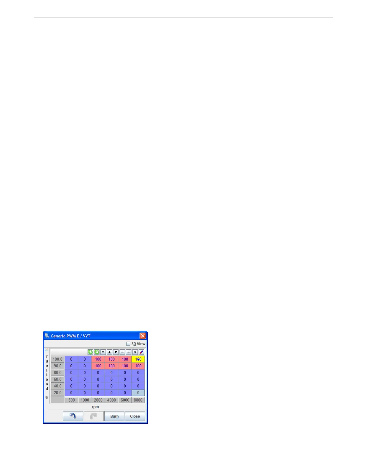
7.6.16 VVT on/off table
For on/off mode, no feedback of cam position is used and most settings on the VVT settings screen are unused
and grayed out. The output value, frequency and injector timing adjustment are set through the main settings
screen. In place of the angle target table, an on/off table is used. In this table, set 100 for cells where VVT should
be active and 0 for cell where it should be inactive. Do not use other values.
AMP EFI MS3Pro manual version 1.202, firmware 1.5.0, 4/21/2017 Page 215