7.3 Ignition Settings 7 ADDITIONAL ITEMS: BEYOND BASIC FUEL AND IGNITION CONTROL
• Bandpass frequency - this should be adjusted to suit the resonant frequency of you engine. (Formulae exist
on the web for estimating this frequency based on bore diameter.)
• Integrator time constant - internal setting to knock sensor chip. Default is 150us. A larger number will
reduce the output level and creates more filtering.
• Number of sensors - how many knock sensors are connected (1 or 2.)
• Monitor per cylinder - when sequential fuel or spark are in operation the code can determine which cylinder
the knock signal applies to. This enables the individual cylinder data to be recorded.
• Gain - compensate for sensor sensitivity and distance between cylinder and sensor.
• Sensor - pick which sensor to use for each cylinder.
Some engines have multiple knock sensors. In this case, you will usually want to pair the cylinder with whichever
sensor is nearest. For example, LS1 style engines use a pair of sensors in the valley which are positioned to
"listen" to four equally spaced cylinders each. i.e. the front sensor corresponds to cylinders 1,2,3,4 and the rear
sensor to cylinders 5,6,7,8.
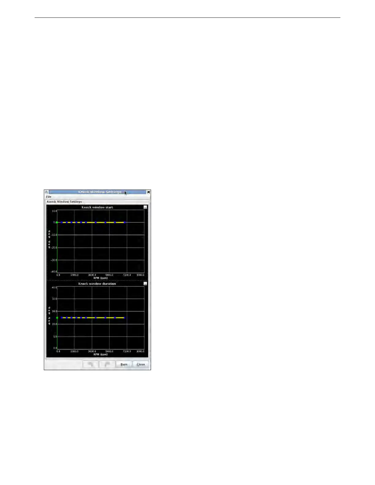
7.3.9 Knock window settings
These are used with both internal and analog knock sensing modes.
The upper chart sets the crank angle to start the knock window on the cylinder being monitored. Positive is
before TDC, negative is after TDC. The lower chart sets how many crank degrees the knock window stays open
for. The defaults reflect that knock events start around top dead center on most engines.
7.3.10 Knock coolant scaling
This screen is used with both internal and analog knock sensing modes.
AMP EFI MS3Pro manual version 1.202, firmware 1.5.0, 4/21/2017 Page 175