5.3 Ignition settings 5 SETTING UP A BASIC CONFIGURATION
This one uses a 12 tooth crank trigger and 3 tooth cam trigger, with VR sensors on both. Supports fully sequential
injection. Note that current code only has the crank trigger angle for V-twins and V-4 motorcycle engines. This
pattern was also used on some inline four motorcycles, but the current code (1.4.0) does not support this yet.
Inline four code is in development and will be added to a future firmware release.
5.3.29 Fiat 1.8 16V
Uses a six tooth crank trigger and a three tooth cam trigger, with a VR crank trigger and Hall effect cam signal.
Both wheels have irregular spacing.
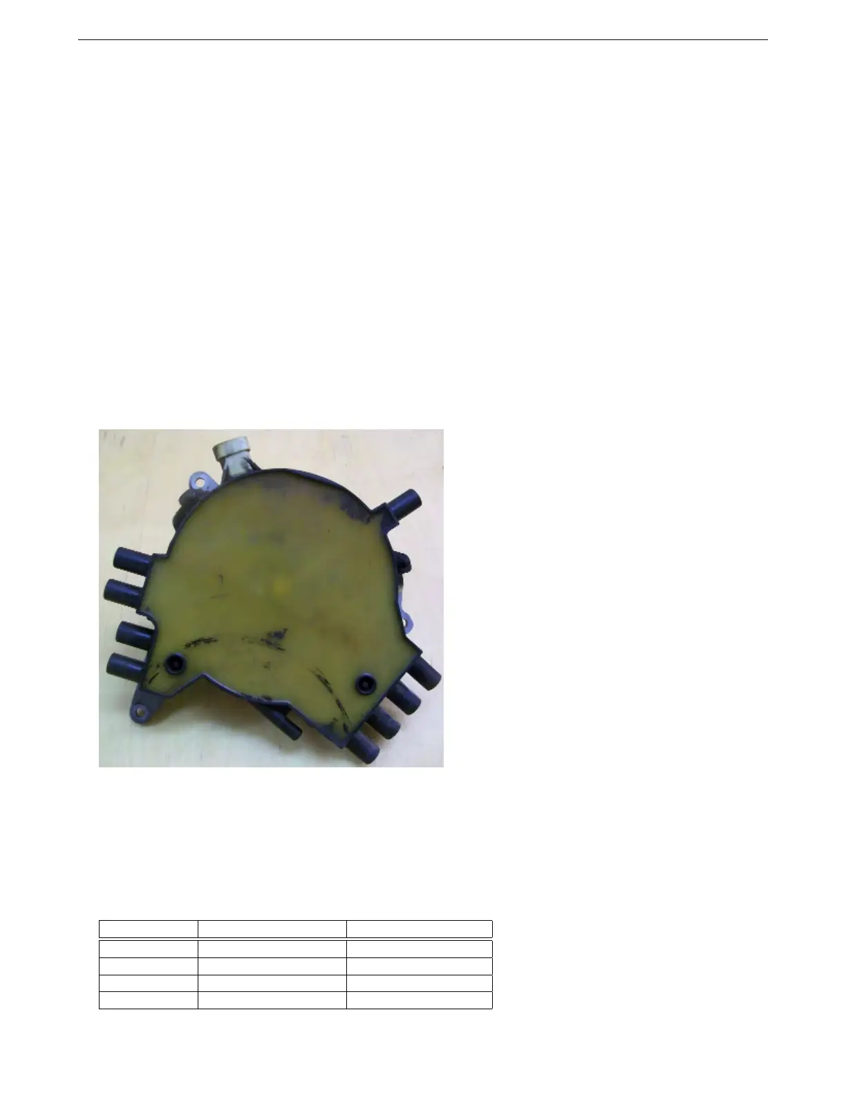
5.3.30 Optispark
Known applications include:
• Chevrolet LT1 variations
• Nissan VH45 V8
The Optispark system was used on GM vehicles from 1993 to 1997 on LT1, LT4 and L99 applications. Internally, it
uses a Mitsubishi / Nissan derived optical trigger arrangement. There is a "hi-res" track of 360 slits and a "low-res"
track of 8 slots of varying length. The pickup design is sound, but the high-tension side can be problematic with
the "correct-a-cap" design - especially if a high energy aftermarket ignition system is used.
The MS3Pro Optispark decoder uses both low and high resolution tracks for improved ignition accuracy. (Most
other aftermarket implementation only use the low resolution track.) The system allows for sequential fuel and the
single coil as per the original install. However, as an enhancement, the single coil can be replaced by a wasted-
spark or coil-on-plug setup to eliminate the troublesome high-tension cap. This lets you keep the stock Optispark
trigger wheel with alternate ignitions.
The Optispark requires a fused 12V supply. This can be tapped into the same 12V supply as the MS3Pro. The
Ground connection should be run to the sensor ground at the MS3Pro. The high and low resolution tach signals
each require a 5 volt "pull up" resistor to operate correctly. The connector is marked with letters that can be used
to identify the functions.
Optispark pin Function Connection
A Low resolution signal CKP+
B High resolution signal Digital frequency in 2
C 12 volt power Shares power
D Ground Sensor ground
AMP EFI MS3Pro manual version 1.202, firmware 1.5.0, 4/21/2017 Page 93