4.12 Grounding notes 4 WIRING
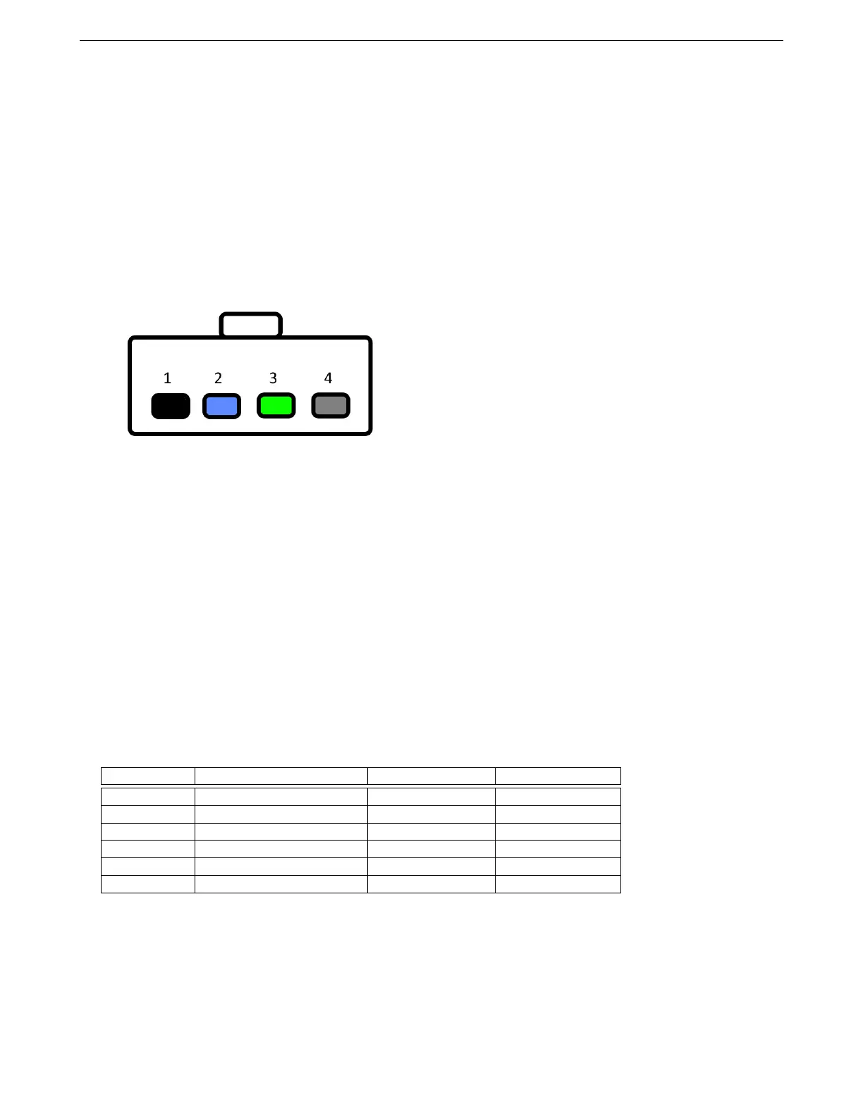
1. Black: Power ground.
2. Blue / Pink: Trigger signal; connect to MS3Pro output.
3. Green: Power output, supplies 12 volts to device being controlled.
4. Gray: 12 volt switched power.
Note that while the Standard Motor Products item uses the OEM Chrysler wiring colors, some other manufacturers
that make OEM replacement parts do not adhere to factory wiring colors and use other color schemes. If you get
one of these - or a connector with uncrimped pins - see the picture below, which is looking into the pins on the
relay with the locking tab facing up.
4.12 Grounding notes
The MS3Pro uses multiple ground planes to reduce noise. It is important that you connect both the logic ground
at pin 16 on the white connector and all the power grounds on the gray connector to the battery negative terminal.
It is less than ideal, but still acceptable in most cases, to ground the MS3Pro to the engine block or cylinder head.
Avoid grounding the MS3Pro to the frame rails or sheet metal; these points often have issues with rust and spot
welds limiting how much current can flow through them.
Leaving the logic ground disconnected can result in improper operation.
The MS3Pro has a sensor ground pin on pin 18 of the white connector. All sensors except VR sensors should
be grounded to this pin. Do not ground the sensors to the chassis, engine block, or other external point, as this
can create noise issues.
4.13 Output comparison chart
These charts show the current charts, clamped voltage, and other key information about the MS3Pro’s different
output circuits.
Name Output type Max rated current Clamping voltage
Injector Low side 5 A 36 V
High current Low side 5 A 36 V
Spark 5V high side 100 mA* N/A
PWM Low side 3 A 12 V
Tach Low side w / 12 V pull up 1 A 12 V
Stepper H-bridge 400 mA peak 12 V
* Do not exceed 250 mA total for all spark outputs at one time.
AMP EFI MS3Pro manual version 1.202, firmware 1.5.0, 4/21/2017 Page 50