4.7 IAC valves 4 WIRING
Typical bipolar steppers have 4 leads, connected to two isolated coils in the motor. These are the most common
in automotive applications. Bipolar permanent magnet and hybrid motors are constructed with exactly the same
mechanism as is used on unipolar motors, but the two windings are wired more simply, with no center taps. The
leads to both coils are brought out to the harness with 4 wires. If you energize one coil the rotor will rotate to a
position aligned with that coil. If you energize the second coil the rotor will rotate a little bit to be aligned between
the two coils. If you turn off the first coil the rotor will rotate a little more to line up directly with the second coil. If you
energize the first coil again with the opposite polarity of the first time the rotor will rotate a little more, and so on.
The MS3Pro controller applies pulses in a particular sequence to the four wires to produce rotation. Each pulse
results in specific amount of rotation of the motor . The motor can be made to spin either direction by changing the
polarity of the pulses.
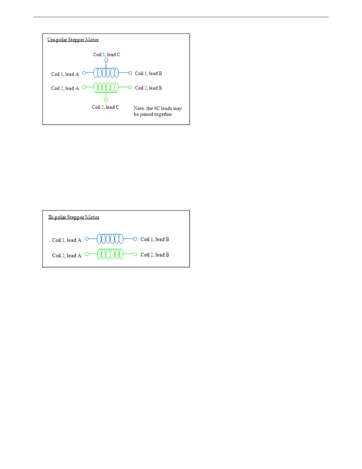
On GM IAC steppers, the one coil usually has blue wires leading to it, the other coil has green wires. The
schematic below shows how such a motor is wired.
The picture below shows most of the common GM and Chrysler IAC valve pinouts and how they wire to the
MS3Pro. The illustration is looking into the IAC valve itself, not the wiring on the harness side.
AMP EFI MS3Pro manual version 1.202, firmware 1.5.0, 4/21/2017 Page 47