12-3 Typical Measurements Balanced Ports, Option 77
12-4 PN: 10580-00289 Rev. K Vector Network Analyzer MG
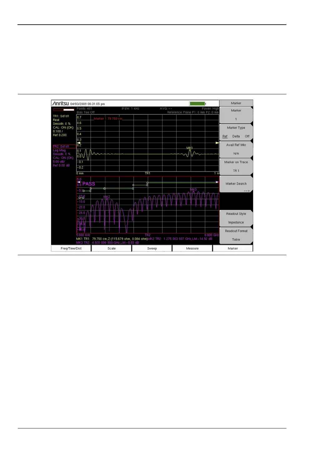
Figure 12-3 shows both the frequency and distance domain responses of the differential cable
under test. Markers are used in the frequency domain to check for the return loss values at
different frequency points. In the distance domain, a marker is used to check the impedance
value at the end of the cable under test. The marker readout can be set independently of the
graph type, and in this case (Figure 12-3), it was set to Impedance. In the example in
Figure 12-3, the impedance readout at the end of that cable is 115 ohm, which is a good
termination for this 100 ohm differential cable.
Figure 12-4 shows a cable that fails its return loss specification limits. Looking at the
distance domain plot, you can see that the cable has a large mismatch at the end of the cable.
The marker reading validates this by providing the impedance value at the end of the cable.
In this case, the results point to an open condition at the end of the cable. With its flexible, yet
powerful display, and with marker and limits capabilities, the Vector Network Analyzer is
able to test differential cables against their specifications, and also it is able to troubleshoot
any failures that are identified.
Figure 12-3. Frequency and Distance Domain Responses of Differential Cable