69
2.4.1.1.2. Connection using Main Connector (Rx diversity)
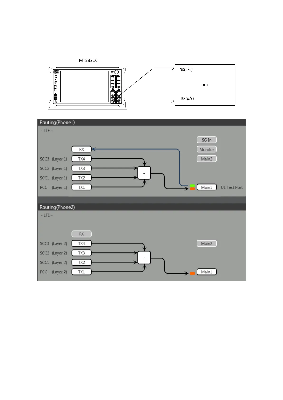
This example shows the connection diagram for 4DL/1UL CA and Rx diversity. The DL signals for PCC, SCC1 SCC2
and SCC3 are combined by the internal combiner of MT8821C and output at both Main1 connector of Phone1 and
Main1 connector of Phone2.
<Connection Diagram>
<Internal Routing Diagram>
Figure 2.4.1-2 Connection Diagram for 4DL/1UL CA, Tx and Rx Test
(MT8821C, antenna configuration set to Rx Diversity)
[Routing setting procedure]
1. Execute ANTCONFIG RX_DIVERSITY to set Common Parameter – Antenna Configuration to Rx Diversity.
2. Execute TXOUT 1, MAIN to set the output connector System Config – Routing(Phone1) – Tx1 to Main.
3. Execute TXOUT 2, MAIN to set the output connector System Config – Routing(Phone1) – Tx2 to Main.
4. Execute TXOUT 3, MAIN to set the output connector System Config – Routing(Phone1) – Tx3 to Main.
5. Execute TXOUT 4, MAIN to set the output connector System Config – Routing(Phone1) – Tx4 to Main.
6. Execute TXOUT_P2 1, MAIN to set the output connector System Config – Routing(Phone2) – Tx1 to Main.
7. Execute TXOUT_P2 2, MAIN to set the output connector System Config – Routing(Phone2) – Tx2 to Main.
8. Execute TXOUT_P2 3, MAIN to set the output connector System Config – Routing(Phone2) – Tx3 to Main.
9. Execute TXOUT_P2 4, MAIN to set the output connector System Config – Routing(Phone2) – Tx4 to Main.
NOTE: When Both the Phone1 and Phone2 LTE measurement software are active, Rx Diversity can be selected at
the Phone1 side only.