System Control
ARM DDI 0388I Copyright © 2008-2012 ARM. All rights reserved. 4-35
ID073015 Non-Confidential
4.3.15 TLB Lockdown Register
The TLB Lockdown Register characteristics are:
Purpose Controls where hardware translation table walks place the TLB entry. The
TLB entry can be in either:
• The set-associative region of the TLB.
• The lockdown region of the TLB, and if in the lockdown region, the
entry to write.
The lockdown region of the TLB contains four entries.
Usage constraints The TLB Lockdown Register is:
• only accessible in privileged modes
• common to Secure and Non-secure states
• not accessible if NSACR.TL is 0.
Configurations Available in all configurations.
Attributes See the register summary in Table 4-11 on page 4-10.
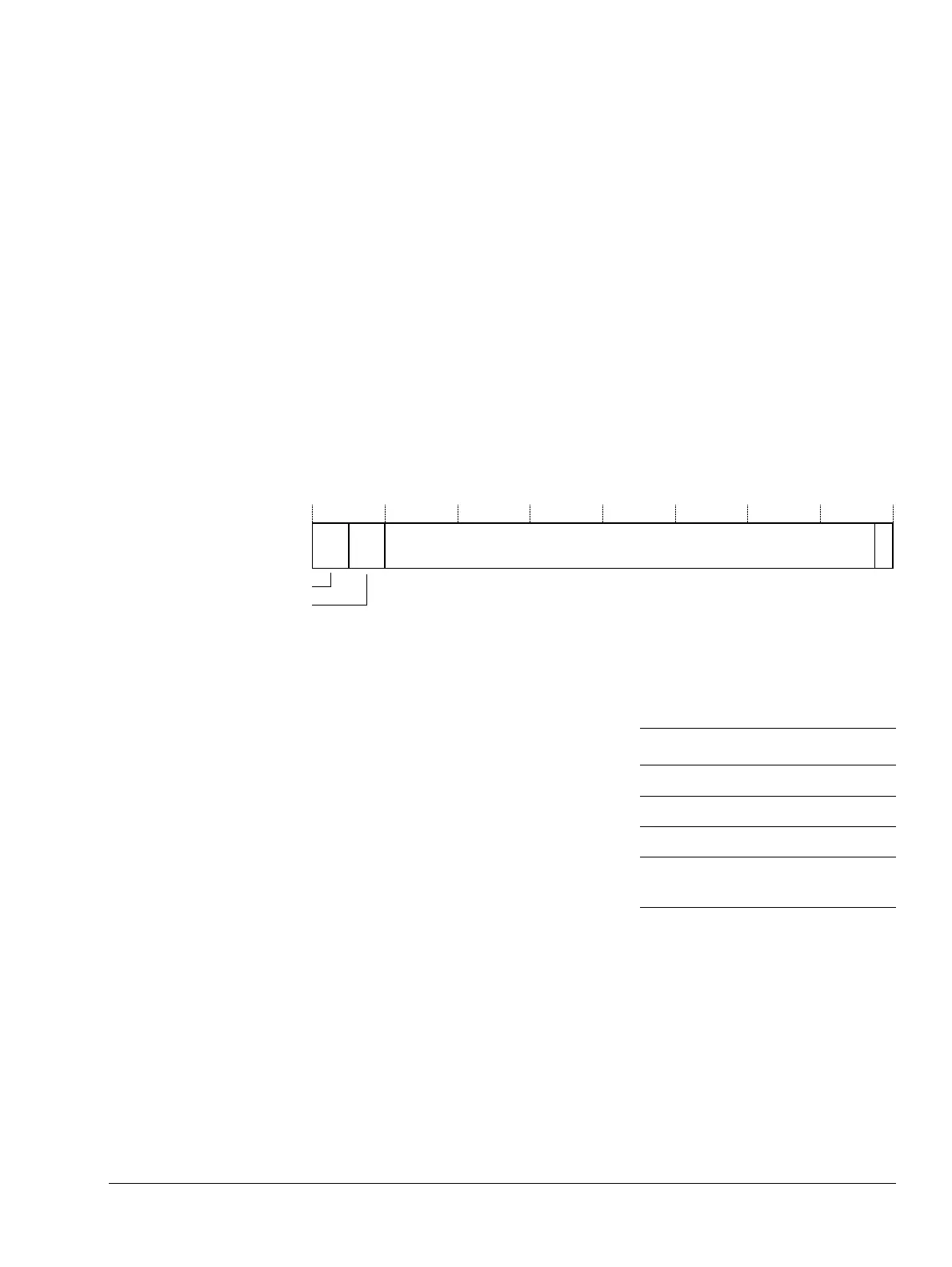
Figure 4-14 shows the TLB Lockdown Register bit assignments.
Figure 4-14 TLB Lockdown Register bit assignments
Table 4-41 shows the TLB Lockdown Register bit assignments
To access the TLB Lockdown Register, read or write the CP15 register with:
MRC p15, 0,<Rd>, c10, c0, 0; Read TLB Lockdown victim
MCR p15, 0,<Rd>, c10, c0, 0; Write TLB Lockdown victim
Writing the TLB Lockdown Register with the preserve bit (P bit) set to:
1 Means subsequent hardware translation table walks place the TLB entry in the
lockdown region at the entry specified by the victim, in the range 0 to 3.
0 Means subsequent hardware translation table walks place the TLB entry in the
set-associative region of the TLB.
See Invalidate TLB Entries on ASID Match on page 4-45.
P
31 29 28 10
UNK/SBZP
30
Victim
27
UNK/SBZP
Table 4-41 TLB Lockdown Register bit assignments
Bits Name Function
[31:30] - UNK/SBZP.
[29:28] Victim Lockdown region.
[27:1] - UNK/SBZP.
[0] P Preserve bit.
The reset value is
0
.