Debug
ARM DDI 0388I Copyright © 2008-2012 ARM. All rights reserved. 10-3
ID073015 Non-Confidential
10.2 About the Cortex-A9 debug interface
The Cortex-A9 processor implements the ARMv7 debug architecture as described in the ARM
Architecture Reference Manual.
In addition, there are:
• Cortex-A9 processor specific events. These are described in Performance monitoring
events on page 11-7.
• System coherency events.
For more information, see Performance monitoring on page 2-3 and Chapter 11 Performance
Monitoring Unit.
The debug interface consists of:
• a Baseline CP14 interface
• an Extended CP14 interface
• an external debug interface connected to the external debugger through a Debug Access
Port (DAP).
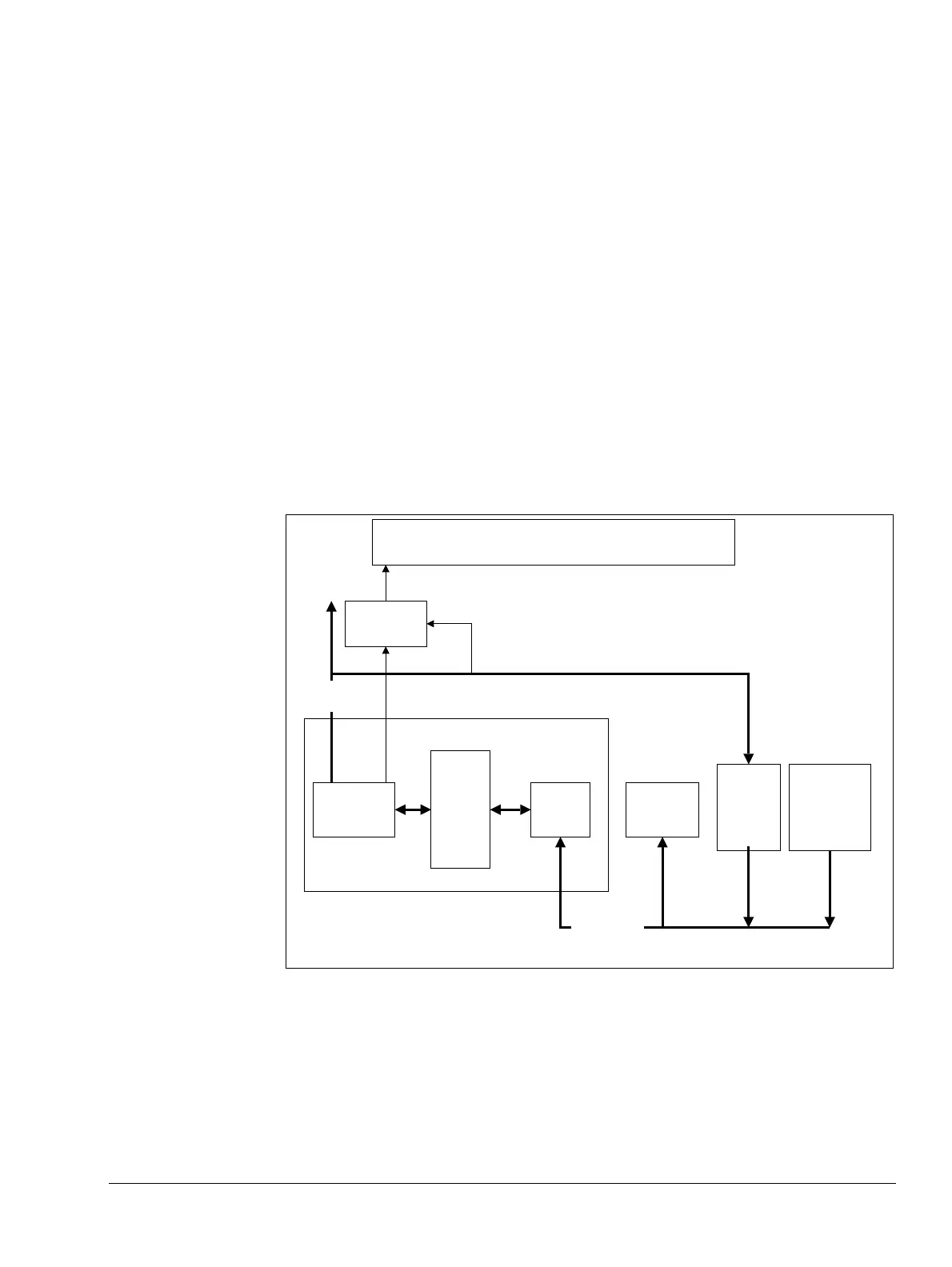
Figure 10-2 shows the Cortex-A9 debug registers interface.
Figure 10-2 Debug registers interface and CoreSight infrastructure
Cortex-A9
processor
Baseline
CP14
interface
and
Extended
CP14
interface
Debug
registers
ROM map
(optional)
Debug
Access
Port
(DAP)
(optional)
System
bus
Vcore power domain
VSoc power domain
Debug APB
Cross-trigger
interface
Cross-trigger
Matrix (CTM)
Debug
Interconnect