5-47
Chapter 5. Functions
5 - 7 Digital Input (DI) / Internal Contacts
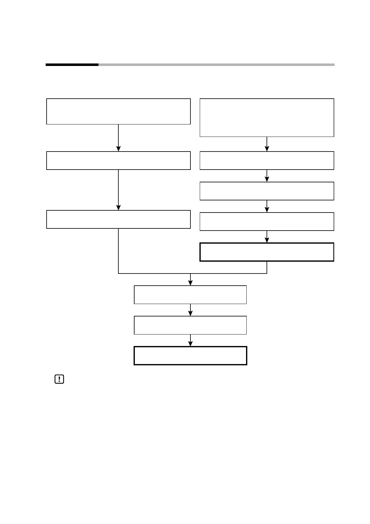
The following is a functional block diagram for digital input (DI) and internal contacts.
Input bit functions are disabled
(DI assignment bank: dI1.2 to dI5.2 (input bit function)
must be set to “0” (not used))
DI status (ON/OFF)
(ON/OFF)
Polarity
(DI assignment bank: dI1.8 to dI5.8)
Input assignment polarity
(DI assignment bank: Polarity A to D: dI1.7 to dI5.7)
Input bit functions 1 to 4
(DI assignment bank: Input bit function: dI1.2 to dI5.2)
Function result polarity
(DI assignment bank: dI1.8 to dI5.8)
Internal contact bit function result
Operation type
(DI assignment bank: dI1.1 to dI5.1)
Internal event No. assignment
(DI assignment bank: dI1.9 to dI5.9)
Internal contact function
When not using input bit functions
Input assignment
(DI assignment bank: Input assignment A: dI1.3 to dI5.3,
DI assignment bank: Input assignment B:dI1.4 to dI5.4,
DI assignment bank: Input assignment C: dI1.5 to dI5.5,
DI assignment bank: Input assignment D: dI1.6 to dI5.6)
When using input bit functions
Handling Precautions
• There are 5 internal contacts, 1 to 5. The number of digital inputs (0, 1, or 2)
can be selected by specifying the appropriate model No. For models with 2
digital inputs, the operation of these inputs is assigned to internal contacts 1
and 2 when the product is shipped.