2-1
Chapter 2. Outline of Functions
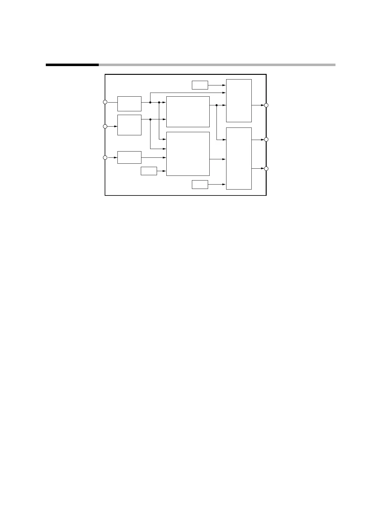
2 - 1 Input/Output Configuration
Other
Digital
output
processing
Analog
output
processing
Control outputs 1–2
(current output)
Control outputs 1–2
(relay output,
Event outputs 1–3
(relay output)
CT inputs 1–2
PV Input
PV
processing
Internal event
processing
Control processing
(ON/OFF control,
PID control)
Other
Other
Internal
contacts
processing
CT
processing
z
PV input
The range and the sensor used for the PV input can be selected. Selectable options
vary depending on the PV input type (T: thermocouple, R: resistance temperature
detector, L: DC voltage/current) specified by the model number (digit
).
z
Control output
If R (relay output) or V (voltage pulse output) is specified by the model number
(digits
and ), ON/OFF control output or time proportional output can
be selected. For time proportional output, the time proportional cycle can be
specified. If C (current output) is specified by the model number (digits and ),
continuous output (analog output) is available, and scaling of the output can be set.
For models with two control outputs, heating and cooling control can be used and
is simple to set up.
z
Event output
For models with optional event outputs (digits
and ), the alarm or control
mode set for the event operation type is output as digital output (DO).
z
Digital input
For models with optional digital inputs (digits
and ), the functions specified by
DI assignment can be switched.
z
Current transformer input
For models with optional current transformer inputs (digits
and ), the heater
burnout alarm can be output from the event output terminals.