9-6
Chapter 9. PLC Link Communication Function
Connectible PLCs
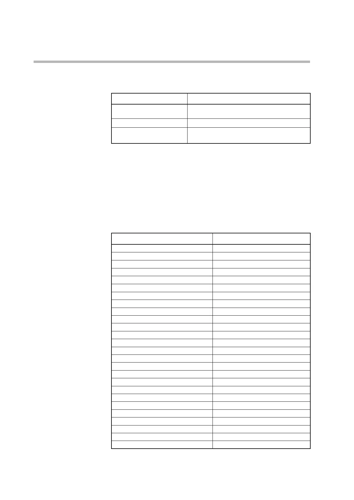
The connectible PLCs are shown in the table below.
Supported protocol Connected device example
Mitsubishi QnA-compatible 3C
protocol format 4
Mitsubishi MELSEC iQ-R, MELSEC Q
Omron FINS (host link) Omron CJ2, CP2
Modbus/RTU Keyence KV-7000, KV Nano
Siemens AG S7-1200
Usable devices
The address ranges of the devices (data) usable with each model are as follows.
z
C1M controller (this device)
Various monitoring data and parameters can be selected in the PLC link settings in
the SLP-C1F Smart Loader Package.
z
Mitsubishi Electric
Device type Address range
Input relay X000000 to X7FFFFF
Output relay Y000000 to Y7FFFFF
Internal relay M000000 to M999999
Special relay SM000000 to SM999999
Link special relay SB000000 to SB7FFFFF
Edge relay V000000 to V999999
Latch relay L000000 to L999999
Link relay B000000 to B7FFFFF
Annunciator F000000 to F999999
Timer (contact) TS000000 to TS999999
Timer (coil) TC000000 to TC999999
Retentive timer (contact) SS000000 to SS999999
Retentive timer (coil) SC000000 to SC999999
Counter (contact) CS000000 to CS999999
Counter (coil) CC000000 to CC999999
Data register D000000 to D999999
Link register W000000 to W7FFFFF
Index register Z000000 to Z999999
File register (R) R000000 to R999999
File register (ZR) ZR000000 to ZR7FFFFF
File register (ZR)(decimal) ZR000000 to ZR999999
Special register SD000000 to SD999999
Link special register SW000000 to SW7FFFFF
Timer current value TN000000 to TN999999
Retentive timer current value SN000000 to SN999999
Counter current value CN000000 to CN999999
Note: The range of available addresses varies depending on the specifications and
settings of the CPU unit.