2-2
Chapter 2. Outline of Functions
2 - 2 Key Operation
Various displays and settings can be called up to the console using keys.
There are two key operation modes, standard and special, which can be selected in the setup bank.
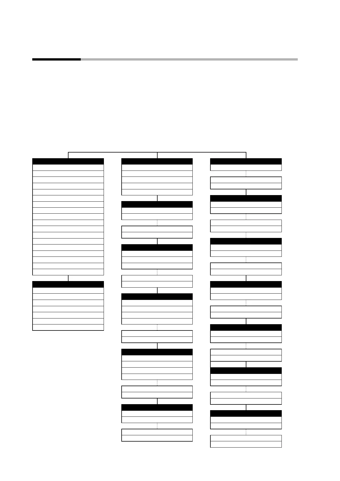
Display transitions and use of keys in each mode are shown below.
Standard mode
If C71 (key operation mode) in the setup bank is set to 0, the keys operate in
standard mode. In this mode, items that can be set are displayed in the order shown
below.
Operation settings Mode Setup
SP
5-95
AUTO/MANUAL
5-11
PV input range type
5-2
LSP No.
5-34
RUN/READY
5-11
Step No., step remaining time
5-38
AT stop/start selection
5-12
PV input failure (under range) type
5-9
MV
5-96
Release all DO latches
5-13
Sampling cycle
6-24
Heat MV
5-96
User-defined bit 1
5-13
Cool MV
5-96
Event configuration
AT progress
5-96
SP Internal event configuration 1
5-62
CT1 current
5-98
LSP group 1 SP
5-33
Internal event configuration 2
5-63
CT2 current
5-98
PID group number (for LSP 1)
6-4
Internal event 1 main setting
5-65
Internal event 5 configuration 2
5-63
Internal event 1 sub-setting
5-65
Ramp (for LSP 8)
5-44
Internal event 5 configuration 3
5-64
Timer remaining time 1
5-97
Soak time (for LSP 8)
5-44
Internal event 2 main setting
5-65
DI assignment
Internal event 2 sub-setting
5-65
Event Internal contact 1 operation type
5-48
Timer remaining time 2
5-97
Internal event 1 main setting
5-65
Internal contact 1 Input bit operation
5-51
Internal event 3 main setting
5-65
Internal event 1 sub-setting
5-65
Internal event 3 sub-setting
5-65
Internal event 1 hysteresis
5-65
Internal contact 5 polarity
5-53
Timer remaining time 3
5-97
Internal contact 5 internal event No. assignment
5-50
Internal event 5 ON delay time
5-66
User function (enabled) Internal event 5 OFF delay time
5-66
DO assignment
User function 1
5-99
Control output 1 operation type
5-71
User function 2
5-99
PID Control output 1 output assignment A
5-72
User function 3
5-99
Proportional band 1
5-21
User function 4
5-99
Integral time 1
5-21
Event output 3 polarity
5-74
User function 5
5-99
Derivative time 1
5-21
Event output 3 latch
5-74
User function 6
5-99
Manual reset 1
5-21
User function 7
5-99
User function
Cool-side MV low limit 8
5-21
User function 1
5-99
Cool-side MV high limit 8
5-21
User function 2
5-99
Parameter User function 7
5-99
Control method
5-16
User function 8
5-99
MV low limit at AT
5-24
MV high limit at AT
5-24
Lock
ON/OFF control differential
5-20
Key lock
5-103
Communication lock
5-103
SP up ramp
5-36
SP down ramp
5-36
Password 1B
5-104
Password 2B
5-104
Extended tuning
AT type
5-24
Instrument information
SP lag constant
5-27
ROM ID
6-40
Note: The number on the right of
the setting items indicates the
page that gives the explanation
of the item.
ROM version 1
6-40
Control algorithm
6-18
Cooling gain
6-18
Advanced function password 15
6-41
Advanced function password 16
6-41