1-4
Chapter 1. Overview
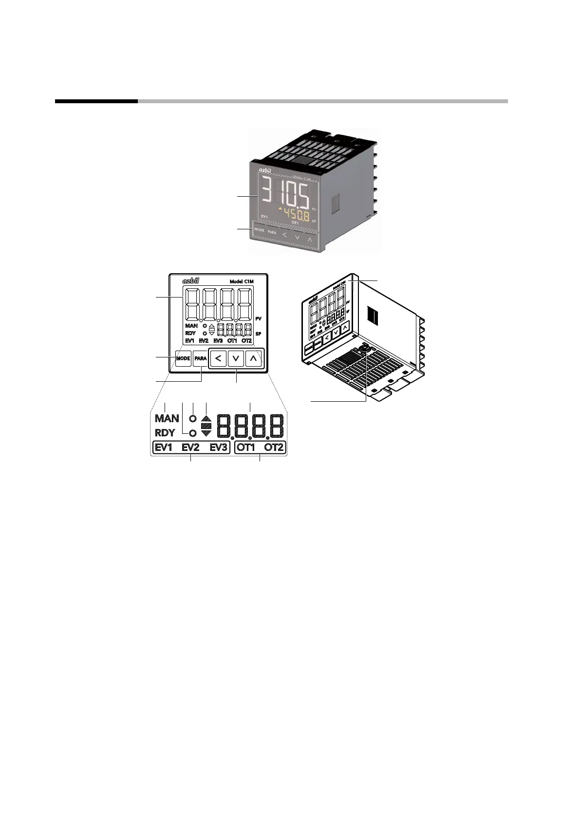
1 - 2 Names and Functions of Parts
Model C1M and its console
Display
(4)
(12)(11)
(5)
(10)
(9)
(13)
(14)
(1)
(2)
(3)
(1) Upper display: Shows PV (present temperature, etc.) or items that can be set.
(2) [MODE] key: Shows the operation display.
If it is held down for 1 second or longer, the preset operation (initial setting: AUTO/MANUAL
selection) can be executed.
(3) [PARA] key: Switches the display.
(4)
[<], [∨], and [∧] keys:
Used for incrementing/decrementing numeric values and shifting between digits of a
number.
(5) MAN mode indicator: Lights up in MANUAL mode.
(6) RDY mode indicator: Lights up in READY (control stop) mode.
(7) Event indicator: Lights up when the corresponding event relay output is ON.
(8) Control output indicator: Lights up when the corresponding control output is ON.
(9) Status indicator: Lights up according to the setting of the status indicator (by default, not used).
(10) AT indicator: Flashes during AT execution.
(11) Slope display Shows the operation status during a step operation.
(12) Lower display: Shows the SP (set temperature, etc.) or other settings.
(13) Loader connector: Connected to the PC using the USB loader cable included with the Smart Loader Package.
(14) Protective film: Protects the surface. Remove the protective film before use.