D-4
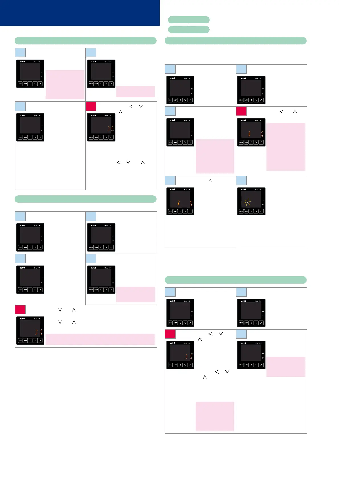
Setup of PV input range type
1
Press [MODE]
once to show the
operation display.
If the sensor has not been
wired or is disconnected,
an alarm for abnormal PV
input (any one from
AL01
to
AL11
) may appear on
the upper display.
2
Hold down [PARA]
for 2 s or longer. The
screen for specifying
parameters is shown
with
a--M
on the
upper display.
In ON/OFF control,
r--r
is on the upper display.
25
0
A--M
AUTO
3
Hold down [PARA]
for 2 s or longer
again.
The setup screen
showing the setting
for
C01
(PV input
range type) is
displayed.
4
Press [ ], [ ], or
[
]. The rightmost
digit on the lower
display flashes and
its value can be
changed.
Select the range
of the sensor (see
the PV input range
table) by pressing [
], [ ], or [ ].
Do not press any
key for 2 s. The new
value stops flashing
and is now set.
C 01
1
C 01
0001
Setup of event operation type
In this example, the operation type of event 1 is set to “deviation high limit.”
1
Press [MODE]
once to show the
operation display.
2
Hold down [PARA]
for 2 s or longer. The
screen for specifying
parameters is shown
with
a--M
on the
upper display.
25
0
A--M
AUTO
3
Hold down [PARA]
for 2 s or longer
again.
The setup screen
showing the setting
for
C01
(PV input
range type) is
displayed.
4
Press [PARA] several
times.
e1.c1
is shown
on the upper display
and
0
on the lower
display.
0
on the lower display
means that no event is
set.
C 01
1
E1.C1
0
5
Press [ ] or [ ]. The rightmost digit on the lower display
flashes.
Press [
] or [ ] until
4
is displayed. Do not press any key
for 2 s. The new value stops flashing and is now set.
4
on the lower display means that the event operation type is “deviation
high limit.”
E1.C1
0004
Use
e2.C1
to set the operation type for event 2, and
e3.C1
for event 3.
Execution of auto tuning (AT)
AT forces ON/OFF of the MV a number of times (a limit cycle) to calculate
PID values. Check that this operation does not create any problems for the
associated equipment before executing AT.
1
Press [MODE]
once to show the
operation display.
2
Hold down [PARA]
for 2 s or longer. The
screen for specifying
parameters is shown
with
a--M
on the
upper display.
25
0
A--M
AUTO
3
Press [PARA] twice.
AT
is shown on the
upper display and
AT.OF
on the lower
display.
If the control method is
ON/OFF control and if bit
3 (AT stop/start display)
of
C73
(mode display
setup) is “0” (disabled),
the parameter and
setting are not displayed.
4
Press [ ] or [ ].
at.Of
flashes.
The display flashes only
in RUN and AUTO modes,
and only if there is no PV
input error.
Also, if “AT stop/start” is
set as the DI assignment,
the display does not flash
and the setting cannot
be changed using the
keys.
AT
At.OF
AT
At.OF
5
Press [ ] once.
at.On
flashes on the
lower display.
6
Do not press any
key for 2 s.
at.ON
stops flashing and
AT begins.
During AT, the AT
indicator flashes
and repeatedly.
When AT and the
calculation of PID
constants are done,
the indicator turns
off.
AT
At.ON
AT
AtON
During the AT process, if the mode is changed to READY or MANUAL, if PV
input is faulty, or if a power failure occurs, AT stops automatically without
changing the PID constants. AT can also be stopped by changing the
setting from
At.ON
to
At.OF
(return to step 3 above).
Setup of the SP
1
Press [MODE]
once to show the
operation display.
2
Check that the
operation display
shows the SP.
(If not, press [PARA]
several times until it
is displayed).
25
0
25
0
3
Press [ ], [ ], or
[
]. The rightmost
digit on the lower
display flashes and
its value can be
changed. Change
to the desired SP by
pressing [
], [ ],
or [
].
Flashing means the
setting has not been
finalized.
If the SP limit function
is enabled, a value
exceeding the limit
cannot be set. If you need
to change the value,
change the SP limit first.
4
Do not press any
key for 2 s. The new
value stops flashing
and is now set.
If [MODE] is pressed while
the setting is flashing, the
status returns to that of
step 1.
25
0120
25
120
Operation Examples
Red letters
: Initial setup procedure
Blue letters
: Procedure during operation