4-8
Chapter 4. Wiring
Connecting solid state relays (SSR)
To drive the SSR, controllers with voltage pulse outputs must be used. Specify a
model No. that includes “V0,” “VC,” or “VV” (codes for control output).
An SSR can be roughly categorized as either a constant-current SSR or a resistance
SSR. The following describes how to connect each type.
z
Constant-current SSR
Check the following specifications of your SSR and the specification of the voltage
pulse output of the C1M.
• Input current (maximum): If it is below the maximum current allowed for the
voltage pulse output, the SSRs can be connected in parallel.
• Operating voltage: Check that the voltage between the voltage pulse output
terminals is within the specified range.
1. Azbil’s PGM10N or PGM10F
This example shows the calculation for the connection of this device and the
PGM10N015.
For connection with other models, check the specifications of the model.
• Input current:
Since the input current is 10 mA or less, up to two units (10 mA × 2 = 20 mA <
24mA [maximum allowable current]) can be connected in parallel.
• Operating voltage:
The input voltage of the SSR is 3.5 to 30 V. Therefore, the voltage between the
terminals is within the specified range.
Voltage between terminals (two PGM10N units)
= Voltage when open − Internal resistance × Total drive current
= 19 V DC ±15 % − 18 Ω ±0.5 % × 20 mA
≈16 to 21 V
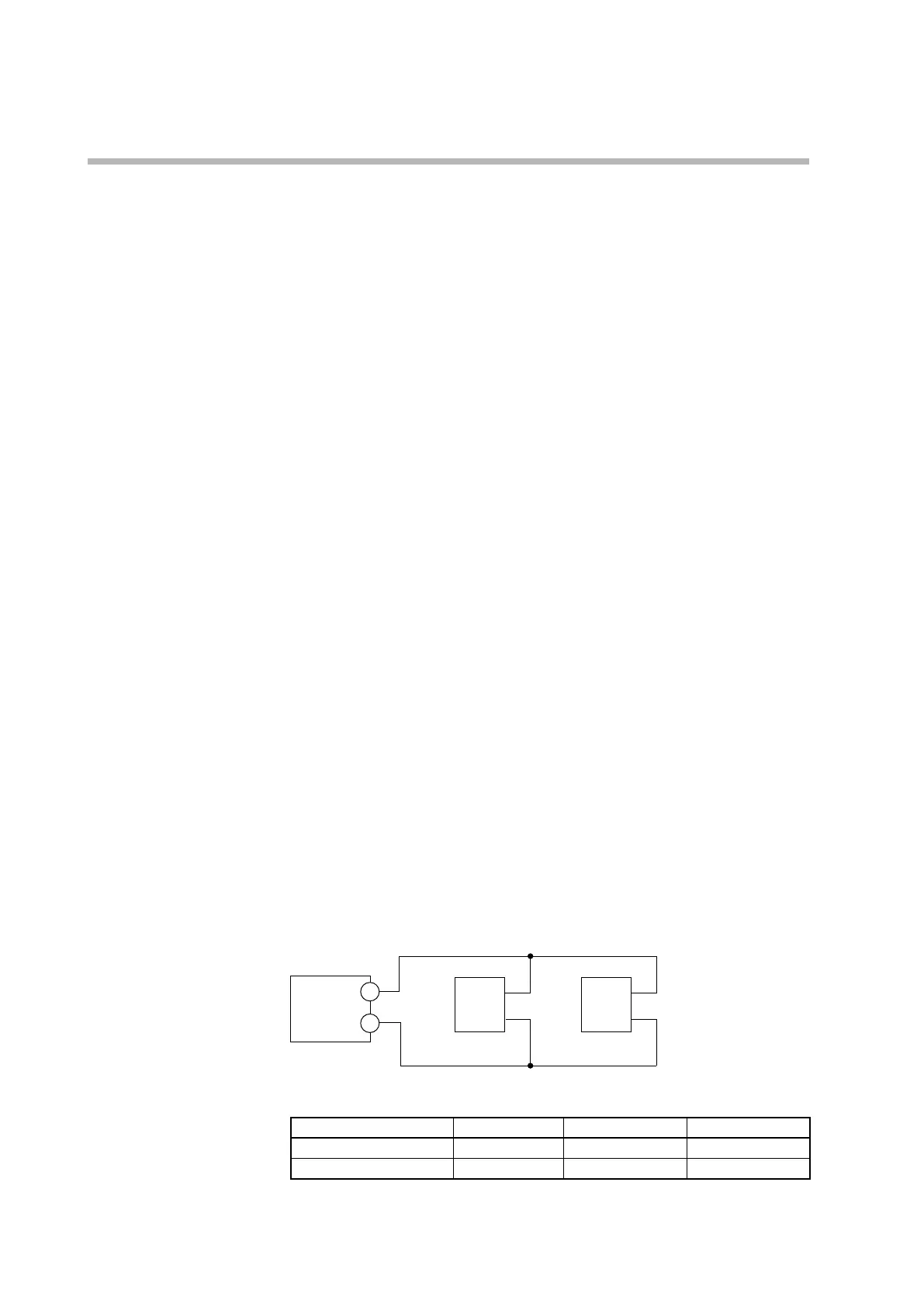
Connection diagram
Model C1M
PGM10N/PGM10F PGM10N/PGM10F
+
−
+
−
+
−
Number of connectable units
SSR Connection V0/VC model VV model
PGM10N
Parallel
2 units max.
4 units max.*
PGM10F
Parallel
2 units max.
4 units max.*
* Two units per output