8-3
Chapter 8. Modbus Communication Function
8 - 2 Message Structure
Message Structure
The following shows the message structure.
All messages are expressed in hexadecimal.
z
Modbus/ASCII
All messages are written in hexadecimal ASCII codes (each slot below represents
one character).
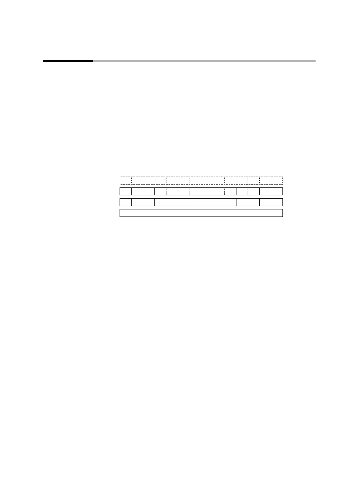
A MODBUS/ASCII message consists of (1) to (5) below.
The command (details sent from the master station) and the response (details
returned from the slave station) are stored in (3).
3AH 0DH 0AH
: CR LF
(1) (2) (3) (4) (5)
1 frame
(1) Start of message (colon, expressed with ASCII code 3AH)
(2) Station address (2 bytes)
(3) Instruction message, response message
(4) Checksum (LRC) (2 bytes)
(5) Delimiter (end of message)
• Colon (3AH)
When a colon (3AH) is received, this device interprets it as the start of a
command message.
No matter what has been received previously, upon receiving a colon, this device
begins processing a new message.
In this way, if an instruction message contains an error due to electromagnetic
noise, etc., this device can respond to the next proper message (a resent message,
etc.) from the master station.
• Station address
This device creates a response message only to instruction messages that mention
its station address. A station address is expressed as a 2-digit hexadecimal
character code in a message.
This device returns a response message that includes its own station address.
The station address can be specified by C65 (station address). Note that, if the
station address is set to 0 (30H 30H), this device does not respond even if the
station addresses match.