1-2
Chapter 1. Overview
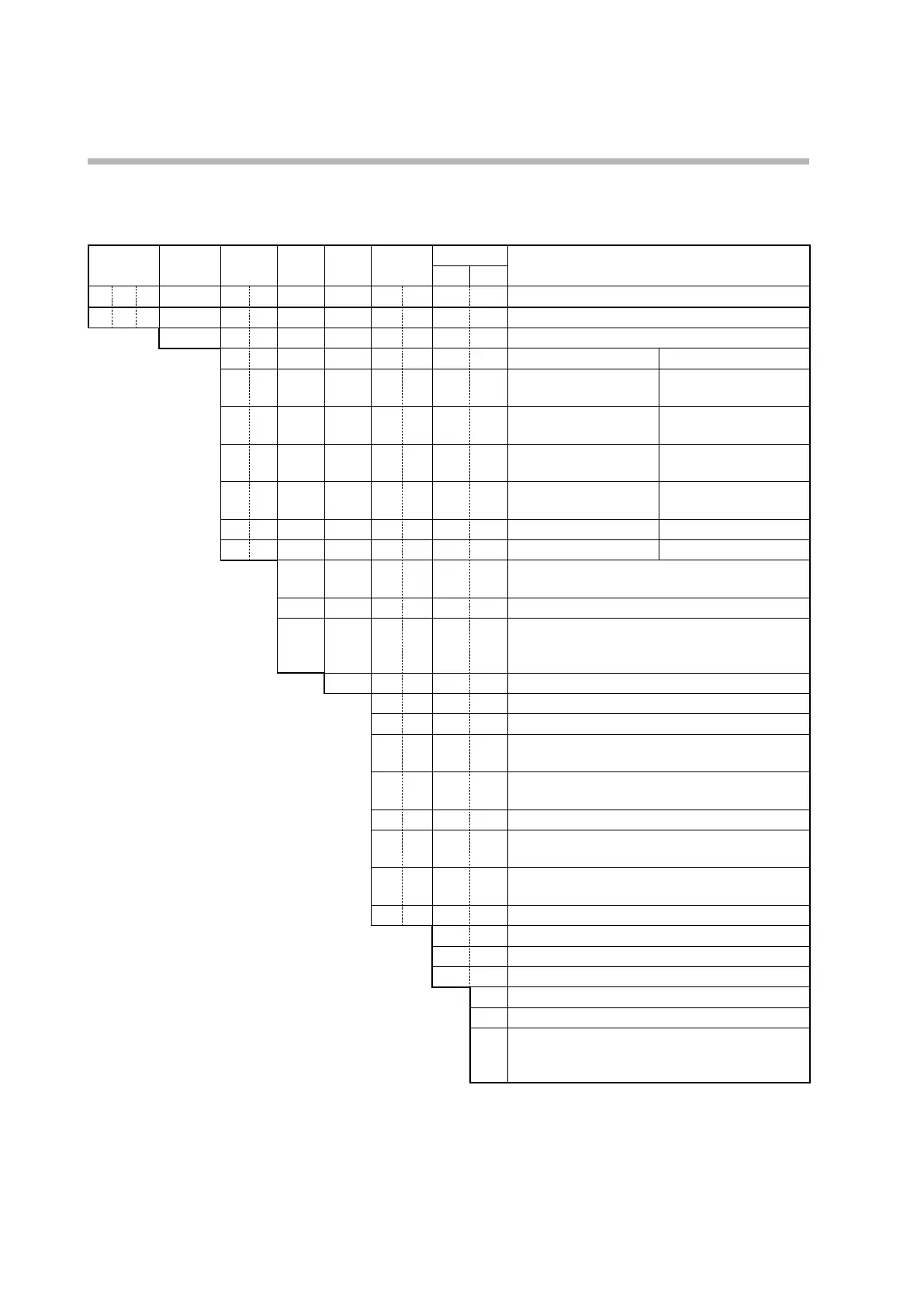
Model Selection Table
Model selection of this device is shown below.
Basic model
No.
Installation
Control
output
PV
input
Power Options
Add'l proc.
Specifications
1 2
Digits
C 1 M Basic model No.
T Screw terminal block
Control output 1 Control output 2
R 0 Relay output
(C.O. contacts)
None
V 0 Voltage pulse output
(for SSR drive)
No
V C Voltage pulse output
(for SSR drive)
Current output
V V Voltage pulse output
(for SSR drive)
Voltage pulse output
(for SSR drive)
C 0 Current output None
C C Current output Current output
T Thermocouple input (K, J, E, T, R, S, B, N, PL II,
WRe5/26, PR40/20, DINU, DINL)
R RTD input (Pt100, JPt100)
L DC voltage/current
(0–1 V, 1–5 V, 0–5 V, 0–10 V DC; 0–20 mA DC,
4–20mA DC)
A AC power supply (100–240 V)
0 0 None
0 1 3 event relay outputs
0 2 3 event relay outputs,
2 current transformer inputs, 2 digital inputs
0 3 3 event relay outputs,
2 current transformer inputs, RS-485 comm.
0 4 2 event relay outputs (independent contacts)
0 5 2 event relay outputs (independent contacts),
2 current transformer inputs, 2 digital inputs
0 6 2 event relay outputs (independent contacts),
2 current transformer inputs, RS-485 comm.
0 9 RS-485 communication
0 None
D With inspection report
Y With traceability certificate
0 None
A UL-compatible model (available soon)
F
UL compatible model
Fahrenheit temperature supportted (available
soon)