6-24
Chapter 6. Displayed Items and Settings
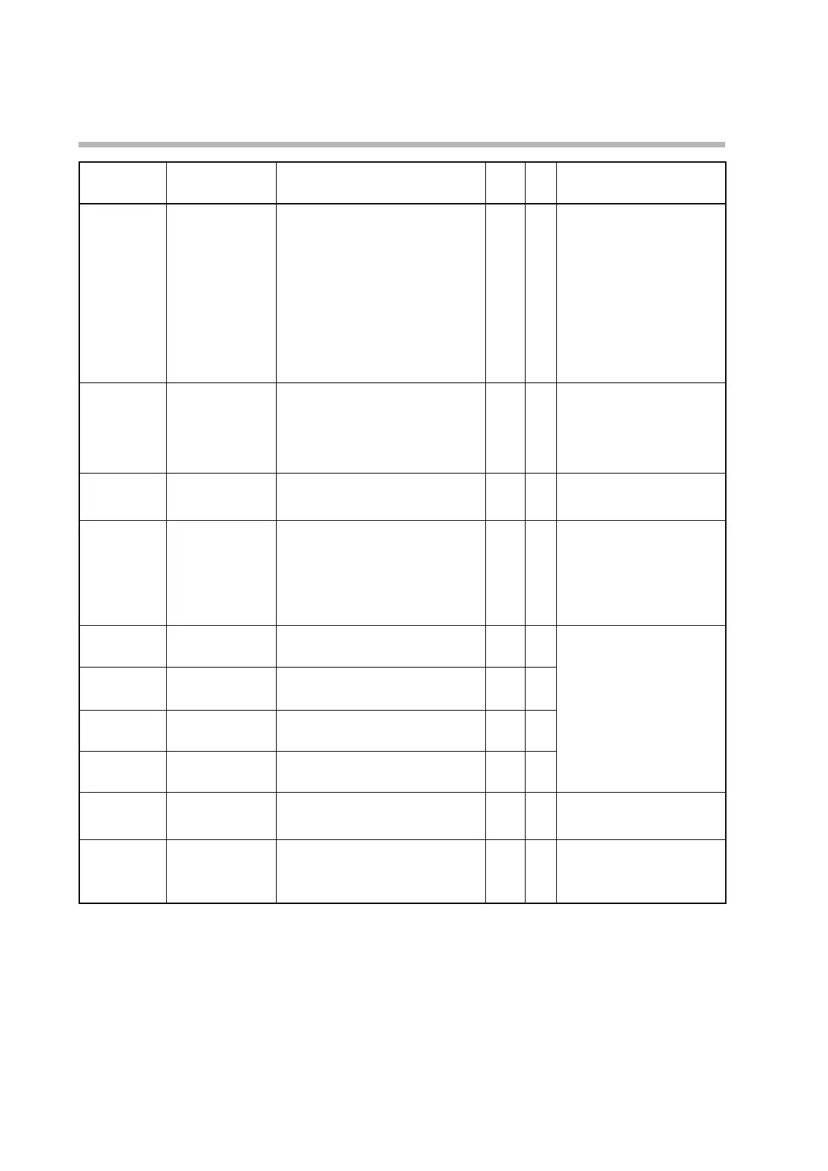
Display Item Description Initial
value
User
level
Notes
C 77
Event remaining
time display setup
0: Do not show the ON/OFF delay
remaining time of internal events on
the operation display
1: Show the ON/OFF delay remaining
time of internal event 1 on the
operation display
2: Show the ON/OFF delay remaining
time of internal events 1–2 on the
operation display
3: Show the ON/OFF delay remaining
time of internal events 1–3 on the
operation display
0 1
C 78
CT input current
display setup
0: Do not show the CT current on the
operation display
1: Show the CT1 current on the operation
display
2: Show the CT1 and CT2 currents on the
operation display
1 1
C 79
User level 0: Simple configuration
1: Standard configuration
2: Advanced configuration
0 0
C 80
Status indicator 0: Not used (always off)
1: Blinks when sending RS-485
communication data
2: Blinks when receiving RS-485
communication data
3: OR (logical sum) of all DI states
4: Always OFF
0 2
C 90
Number of CT1
turns
0: 800
1–40: CT turns divided by 100
8 2 Displayed if a model with two CT
inputs is used.
C 91
Number of CT1
power wire loops
0: 1
1–6: The set value
1 2
C 92
Number of CT2
turns
0: 800
1–40: CT turns divided by 100
8 2
C 93
Number of CT2
power wire loops
0: 1
1–6: The set value
1 2
C 97
PV input failure
(under range) type
0: −10 % FS
1: −5 mV (valid only when C01(PV input
range type) is set to 17 or 23.)
0 0
C 98
Sampling cycle 1: 50 ms
2: 100 ms
3: 300 ms
4: 500 ms
1 2