5-68
Chapter 5. Functions
5 - 9 Digital Output (DO)
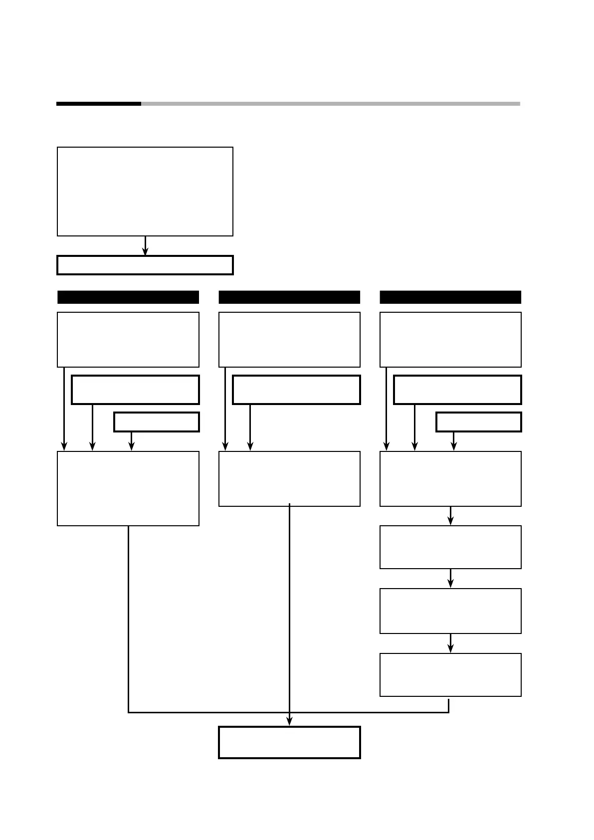
The following is a functional block diagram for digital output (DO).
MV1 processing:
ON/OFF control output, time proportional
output, heating time proportional output
of heating/cooling control
MV2 processing:
Cooling time proportional output of
heating/cooling control
(Parameter bank:
Cy, Cy2, tP.ty)
MV1 and MV2 control output status
When using the default output When using control output When using output assignment
Default output
(DO assignment bank:
Ot1.1
,
Ot2.1
,
Ev1.1
to
Ev3.1
must be set to “default
output”)
Control output
(DO assignment bank:
Ot1.1, Ot2.1,
Ev1.1 to Ev3.1 must be set to “MV1” or
“MV2”)
Output assignment
(DO assignment bank:
Ot1.1
,
Ot2.1
,
Ev1.1
to
Ev3.1
must be set to
one of functions 1 to 4)
MV1 and MV2 control output
status
MV1 and MV2 control output
status
MV1 and MV2 control output
status
Internal event status Internal event status
Output from each DO (terminal)
Control output: MV1
Control output: MV2
Event output 1: internal event 1
Event output 2: internal event 2
Event output 3: internal event 3
Output from each DO (terminal)
(DO assignment bank:
Ot1.1
,
Ot2.1
,
Ev1.1
,
Ev2.1
,
Ev3.1
)
Output assignment and polarity
(DO assignment bank: output
assignment A to D:
Ot1.2
to
Ot2.6
,
Ev1.2
to
Ev3.6
)
Output bit functions 1 to 4
(DO assignment bank: operation
type:
Ot1.1
to
Ot2.1
,
Ev1.1
to
Ev3.1
)
Function result polarity
(DO assignment bank: polarity:
Ot1.7
to
Ot2.7
,
Ev1.7
to
Ev3.7
)
Output latch
(DO assignment bank: latch:
Ot1.8
to
Ot2.8
,
Ev1.8
to
Ev3.8
)
Control outputs 1 to 2
Event outputs 1 to 3