6-29
Chapter 6. Displayed Items and Settings
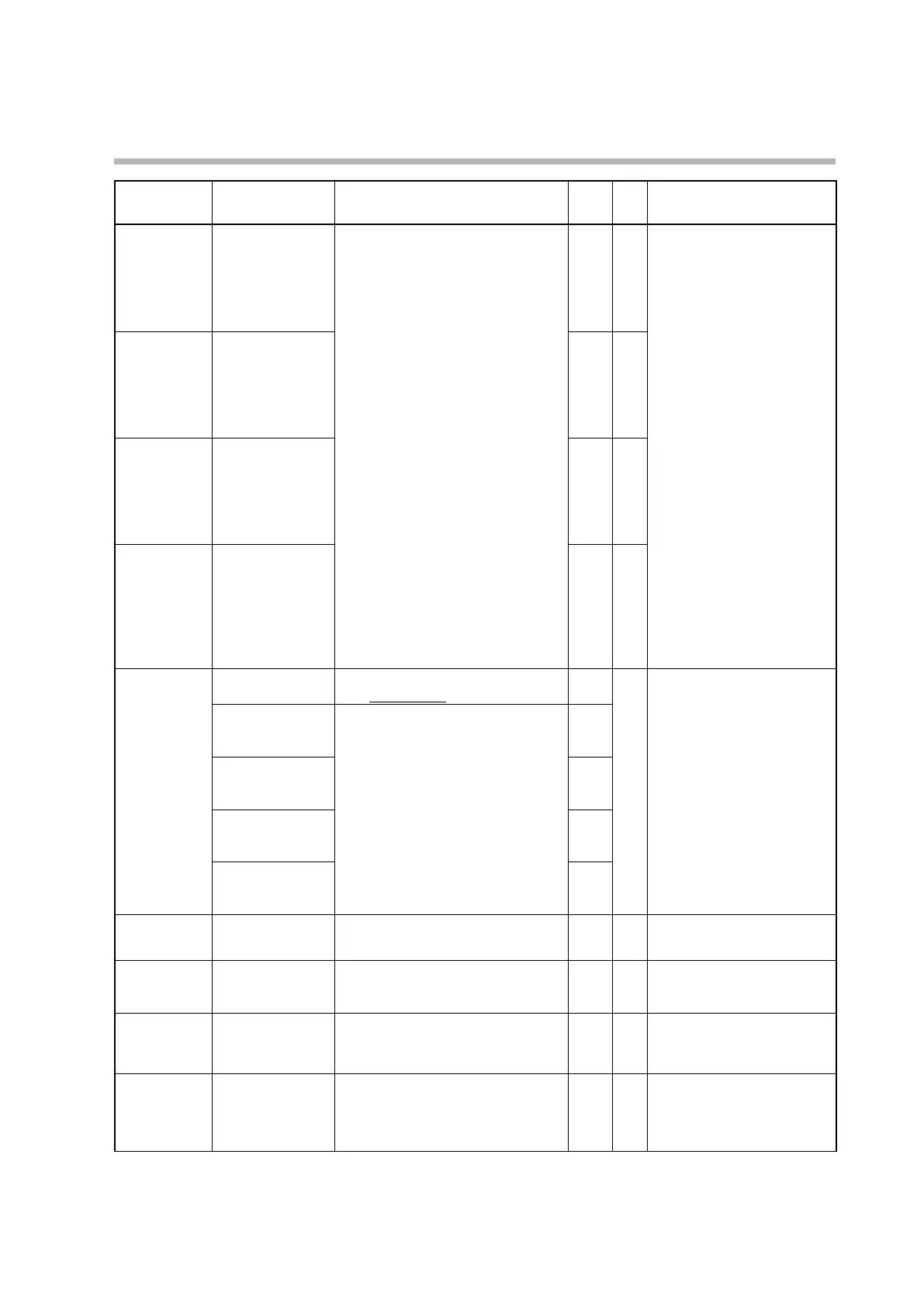
Display Item Description Initial
value
User
level
Notes
DI1.3
Internal contact 1
input assignment A
0: Normally open (normally off = 0)
1: Normally closed (normally on = 1)
2: DI1
3: DI2
4 to 9: Invalid
10: Internal event 1
11: Internal event 2
12: Internal event 3
13: Internal event 4
14: Internal event 5
15 to 17: Invalid
18: User-defined bit 1
19: User-defined bit 2
20: User-defined bit 3
21: User-defined bit 4
22: MANUAL
23: READY
24: Invalid
25: AT (Auto-Tuning)
26: During SP ramp
27: Invalid
28: Alarm
29: PV alarm
30: Invalid
31: [MODE] key status
32: Event output 1 terminal status
33: Control output 1 terminal status
2 2 Displayed if internal contact 1
input bit function is set to one of
functions 1–4 (DI1.2 ≠ 0).
DI1.4
Internal contact 1
input assignment B
0 2
DI1.5
Internal contact 1
input assignment C
0 2
DI1.6
Internal contact 1
input assignment D
0 2
DI1.7
Internal contact 1
polarity A to D
“1st digit” (2nd, etc.) means the first digit
(etc.) from the right.
2 Displayed if internal contact 1
input bit function is set to one of
functions 1–4 (DI1.2 ≠ 0).
1st digit: Polarity A
(polarity of input
assignment A)
0: Direct
1: Reverse
0
2nd digit: Polarity B
(polarity of input
assignment B)
0
3rd digit: Polarity C
(polarity of input
assignment C)
0
4th digit: Polarity D
(polarity of input
assignment D)
0
DI1.8
Internal contact 1
polarity
0: Direct
1: Reverse
0 2
DI1.9
Internal contact 1
internal event No.
assignment
0: All internal events
1 to 5: Internal event No.
0 2 Displayed if internal contact 1
operation type is set to timer
stop/start (DI1.1 = 17).
DI2.1
Internal contact 2
operation type
Same as internal contact 1 operation
type
0 to 20
0 0
DI2.2
Internal contact 2
input bit function
Same as internal contact 1 input bit
function
0: Not used (use the default input)
1-4: Functions 1-4
0 2 If a model with digital inputs is
used, if 0 (not used) is selected,
internal contact 2 reflects the
state of digital input 2.