9-3
Chapter 9. PLC Link Communication Function
9 - 2 Data Transmission
PLC link communication is a function for transferring data between the PLC and this controller. There are two
transfer types: “Cyclic data transfer” and “Triggered data transfer.”
The type of transfer can be set in the PLC link settings of the SLP-C1F Smart Loader Package.
The upper limits for the number of transfer processes and number of sheets are shown below.
Function Maximum No. of
sheets
Maximum No. of
processes in 1 sheet
Total maximum No. of
sheets for the function
Total maximum No. of
processes for the
function
Cyclic data transfer 4 sheets 64 lines 4 sheets 64 lines
Triggered data transfer 4 sheets 64 lines
z
Cyclic data transfer
Data from the controller can be transferred to the PLC periodically. Data can also
be transferred from the host device to the controller.
Major applications:
• Saving controller data to the PLC
• Monitoring controller data by the PLC for device management
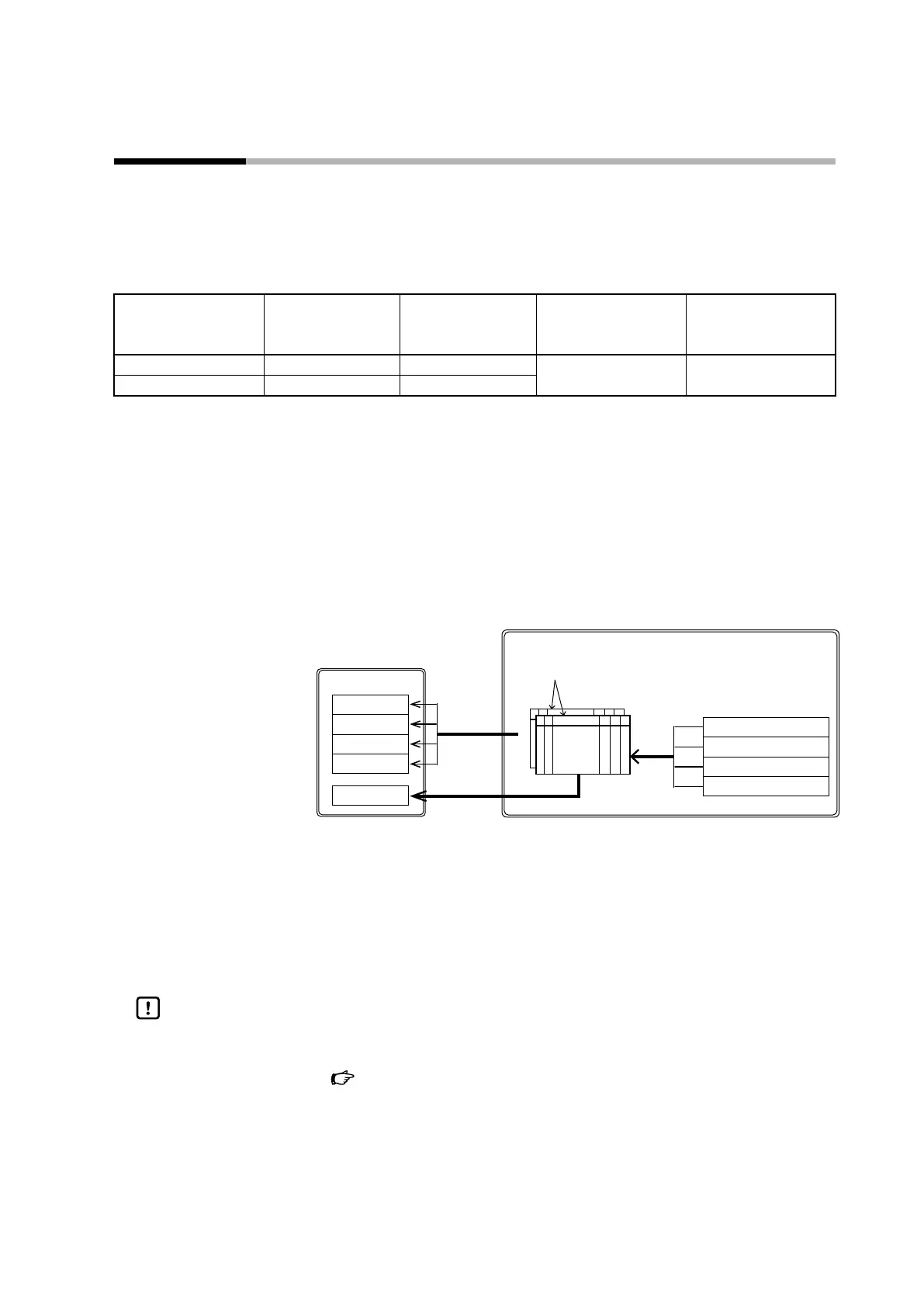
The controller transfers data periodically as follows.
PLC
Model C1M
D0000
D0001
D0002
D0003
M0010
(2) Read
(1) Cyclic start of data transmission
(3) Write
PV
MV
Input alarm status
Instrument alarm status
(1) The controller starts cyclic data transfer according to the configuration sheets.
(2) Data is read from the controller.
(3) The read data is written to the PLC.
(4) When transfer of the data specified for the sheet is complete, a completion
notification is written.
Handling Precautions
• The normal memory area and RAM area are available for the data written from
the PLC to the C1M.
Chapter 10. List of Communication Data (for details)