5-25
Chapter 5. Functions
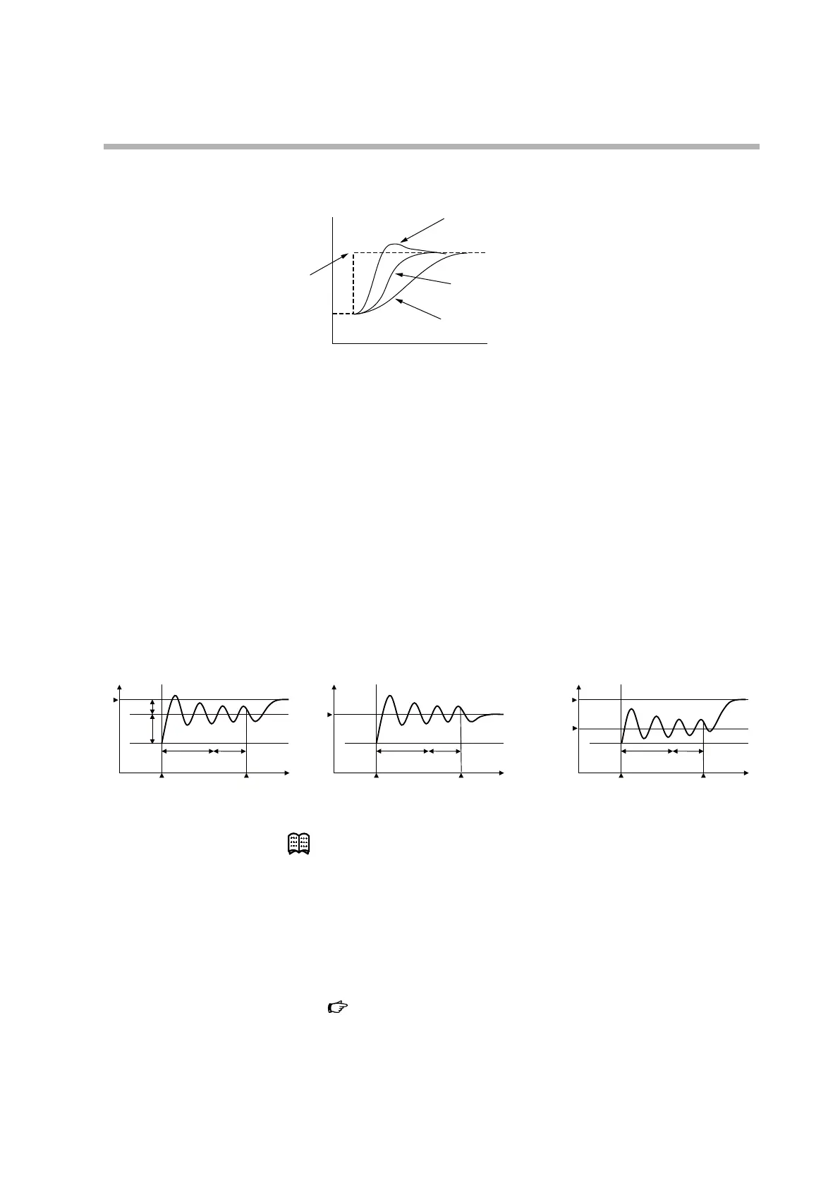
The following graph illustrates the differences in control results using PID constants
calculated with each AT type.
Time
Dierence in PV change when SP is changed
SP
AT type = 1 (immediate response)
AT type = 0 (normal)
AT type = 2 (stable)
• “AT proportional band adjust” (At-P), “AT integral time adjust” (At-I), “AT
derivative time adjust” (At-d):
The PID constants calculated with AT are multiplied by these factors before being
written to the PID constant settings. Note that values within the setting range of
the PID constants will be written.
• “Type of MV switching point at AT” is a setting for changing the MV switching
point during AT.
0 (default): A new MV applies when the PV passes the two-thirds point in the
amount of PV deviation from the SP at the start of AT.
1 (SP): A new MV applies when the PV passes the SP at the start of AT.
2 (PV): A new MV applies when the PV passes the setting for “MV switching
point PV in AT.”
Succeeded
Time
Unstable
Stable
cycle
Stable
cycle
Stable
cycle
2/3
1/3
P
Succeeded
Time
Unstable
SP
Succeeded
Unstable
SP
PV
Type of MV switching point at AT = 0 (default) Type of MV switching point at AT = 1 (SP)
Type of MV switching point at AT = 2 (PV)
AT start AT start
MV switching
point PV in AT
Note
• If you want to execute AT only for heating PID constants when C26 (heat/
cool control ) is set to 1 (use (individual PID)), the settings should satisfy:
50.0 % < MV low limit at AT (At.OL) < MV high limit at AT (At.OH)
If you want to execute AT only for cooling PID constants, the settings should
satisfy:
MV low limit at AT (At.OL) < MV high limit at AT (At.OH) < 50.0 %
AT (automatic tuning) stop/start (p.5-12)
5 - 4 AT (Automatic Tuning) Function (p.5-28) (for details on AT)