SERIAL LINKS 161
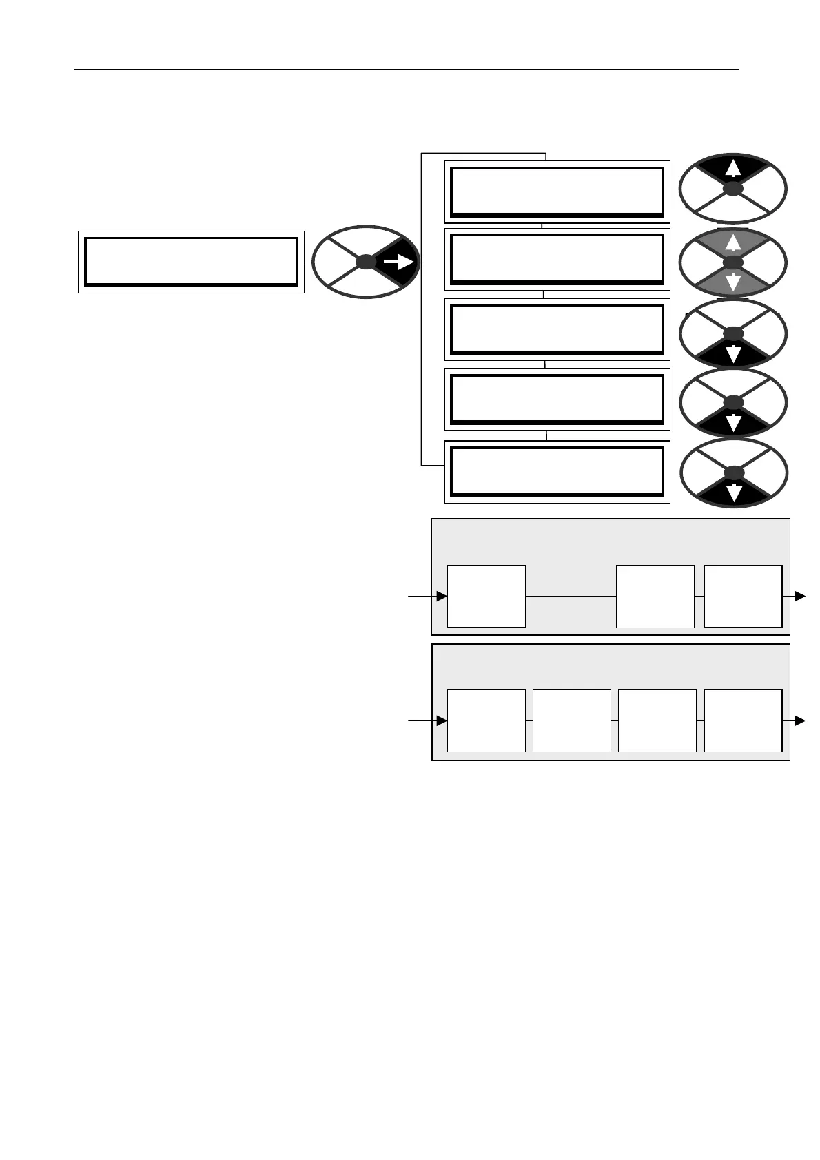
RS232 PORT1 3
REFERENCE EXCH A NGE 4
REFERENCE EXCH A NGE 4
GET FROM
REFERENCE EXCH A NGE 4
189)REF X C SLV RA TIO
REFERENCE EXCH A NGE 4
190)REF X C SLV SIGN
REFERENCE EXCH A NGE 4
191)REF X C SLA VE MON
REFERENCE EXCH A NGE 4
192)REF X C M ASTER MN
10.3 RS232 PORT1 / PORT1 REF EXCHANGE
Allo ws the accurate transmission of parameters
(typically a reference) betw een units with the same
0V. (The slave/master mode is set by PORT1
FUNC TION).
In M ASTER mode the unit initiates high bandwidth
transmission of data, and can also receive data.
In SLA VE mode the unit waits to receive data and
then immediately transmits its ow n data.
Using a GETFROM to source the transmit data, and
and a GO TO to target the received data, within
each PL/X in the chain, gives ultimate flexibility to
the user. See 13.2 Configurable connections.
This function could of course be implemented by using
an analogue signal connection bet w een the drives.
How ever if the system requires greater speed and
accuracy, then this method may be employed.
See 10.1.1 RS23 2 PORT1 / Connection pinouts
for details of the transmit / receive connections.
Daisy chain. When using more than 2 units,
connect RS232 PORT 1 to an external terminal
block to separate the transmit and receive
connections. E.g. from M ASTER transmit to
SLA VE1 receive, and from SLAVE1 transmit to
SLA VE 2 receive etc. The last SLA VE transmit
can connect to the MA STER receive if desired.
With 2 units, the M A STER may use spare SLA VE
blocks. (Send an input, and receive the output).
For information about transmission errors see 8.1.11.15 DRIVE TRIP MESSA GE / Bad reference exchange.
Multi Drive Digital speed locking. Daisy chain using reference exchange and encoder feedback for each drive.
When using this for digital speed accuracy, it is important that the remaining analogue inputs do not inject
small errors into the loop when they are dormant. See 6.7 CH A NGE PARA METERS / SPEED CONTROL.
Useful tips for eliminating unw anted analogue references.
1) The RUN M ODE RA MP output will remain at precisely zero providing the Ramp Hold (T 16) input is
permanently high and the ramp is not permanently preset to a non-zero value. The ramp input may often be
used by line master drives, but in the slave drive the ramp should be disabled using T16. Note that the
incoming digital reference may be passed through the ramp function by re-configuring the appropriate internal
PL/X connections. In this case, the analogue input to the ramp (terminal T4) is disconnected.
2) Analogue input 2 (T2) may be used for inching references. In which case it should be re-connected
via input 1 of the SUMMER 1 apps block, which possesses a deadband function. During normal running, the
terminal is shorted to O V or left open circuit. This ensures no signal passes if the input remains within the
deadband. The analogue inch reference is set above the deadband so as to give the required inching speeds,
forward or backw ard. Selection bet ween analogue inching and absolutely zero is thus automatic. If T2 is not
being used it may be dis-connected, or the UIP2 scaler on PIN 32 2 should be set to 0.0000.
3) Zero input 3 (T 3) using 6.6.7 SPEED REF SUMMER / Speed/Current Reference 3 ratio PIN 67.
RECEIVE. (In SLA VE mode, receiving data triggers
an immediate transmission sequence)
Ratio
PIN 189
+ /-Sign
PIN 190
Slave
monitor
PIN 191
Ref exch
Slave
Goto
TRA NSMIT. (Initiated by the PL/X in Master mode
or by receiving data in SLA VE mode)
Getfrom
RS232
PORT 1
Master
Monitor
PIN 192