76 CHA NGE PARA METERS
6.2.15 RUN M ODE RA MPS / Ramping threshold PIN 34
Until the output of the ramp is within this % tolerance of its target value then 3 5)RA MPING FLAG is high.
This is also true if the ramp is being held at a value that differs from the input by more than the threshold.
See 6.2.16 RUN MODE RAMPS / Ramping flag PIN 35.
6.2.16 RUN M ODE RA MPS / Ramping flag PIN 3 5
The ramping flag may be used to modify the speed loop integrator during ramping.
See 6.7.7.5 SPEED PI A D APTION / Integral % during ramp PIN 78.
Note. 78)INT % DURING RAMP does not reset the integrator, it merely alters the % of integration.
For very precise performance at the ramp end points, e. g. stopping, it is useful to be able to RESET the
SPEED LO OP integrator during the ramping process. By holding it in RESET during the ramping process there
is no undesirable integral history to intefere with the loop at the end of the ramp.
This RESET can be achieved by connecting a JUMPER from 35)RA MPING FLA G to 73)SPEED INT RESET.
See 13.2.4 JUMPER connections.
This monitoring windo w is able to branch hop to 6.2.2 RUN M ODE RA MPS / Ramp output monitor PIN 21.
Digital output DOP2 on terminal 23 is connected by default to the 35)RA MPING FLA G.
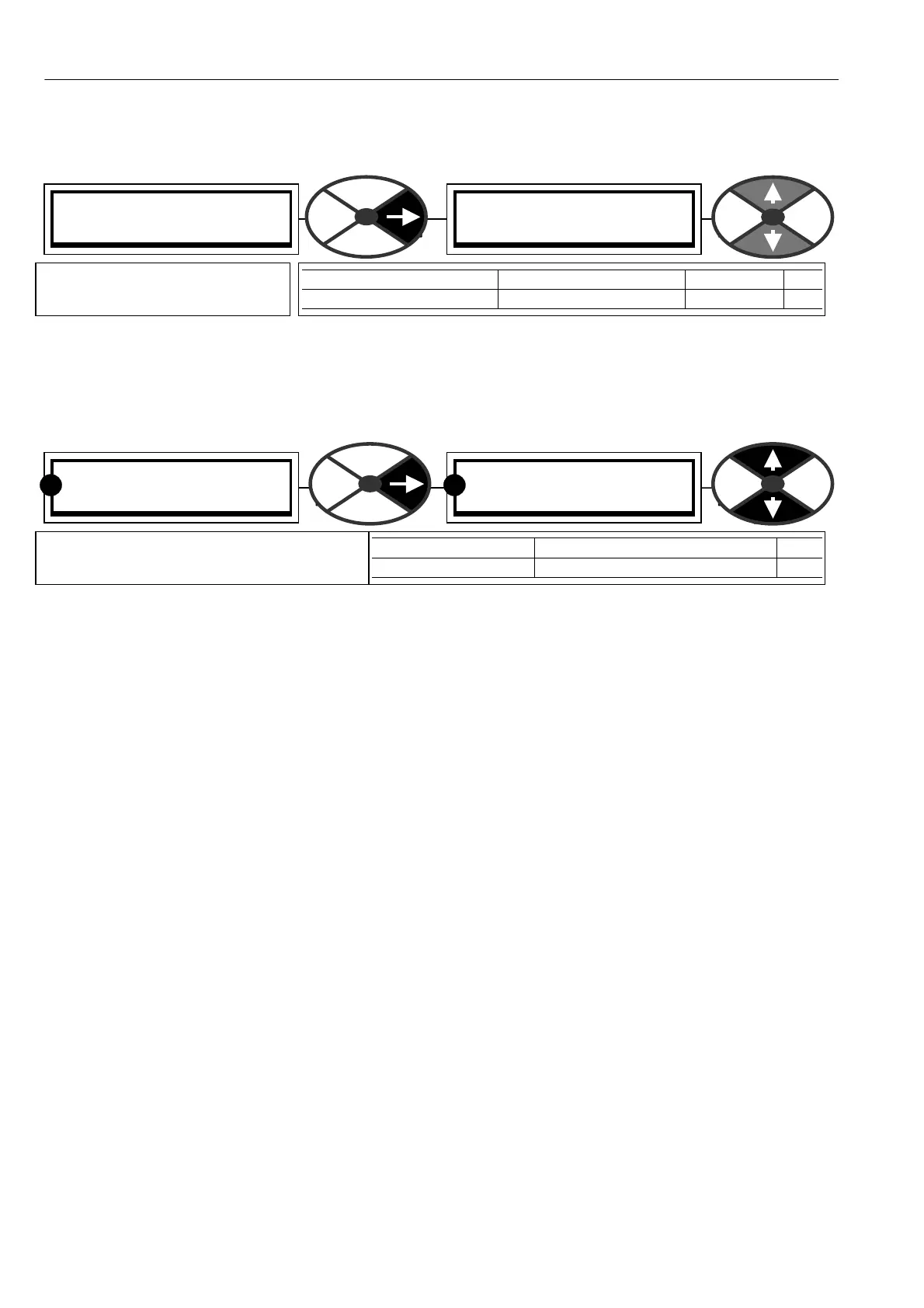
RUN MODE RAMPS 3
34)RA MPING THRESHOLD
34)RA MPING THRESHOLD
2.50%
PARA METER RANGE DEFAULT PIN
RA MPING THRESH OLD 0.00 to 100.00 % 2.50 % 34
Sets the operating threshold for
35)RA MPIN G FLAG output.
RUN MODE RAMPS 3
35)RA MPIN G FLAG
35)RA MPIN G FLAG
LOW
PARA METER RANGE PIN
RA MPING FLA G HIGH or LO W 35
Allo ws the output status of the ramping
flag to be monitored. (HIGH = RA MPIN G)
RR