1 689 988 262 2017-12-26| Robert Bosch GmbH
Product description | EPS 625 | 47 en
MAINS ON
M/C LIGHT
OF
F
ON
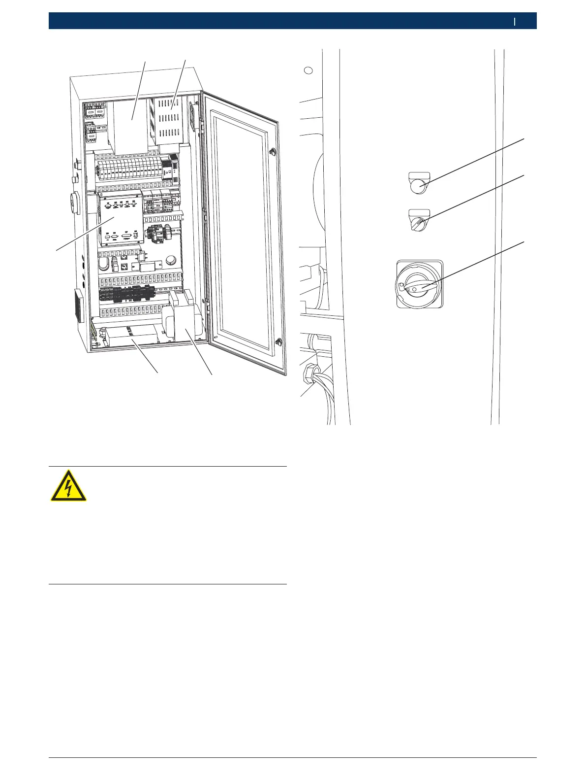
Fig. 8: Side view of the control cabinet
1 "Mains on" indicator
2 MGT illumination switch
3 Master switch
The master switch (Fig8,Pos3) and MGT illumination
switch (Fig8,Pos2) are located on the side of the con-
trol cabinet.
i The bushing (Fig. 1, Pos. 8) acts as a lead-through
for an additional 230 V AC power supply at the
switch cabinet. Customer service must be called
in for wiring up the 230 V AC power supply in the
switch cabinet. Do not alter the wiring in the switch
cabinet. Bosch cannot accept any liability for dam-
age resulting from inexpert workmanship.
1
4
458868_47Nkv
Fig. 7: Control cabinet
1 Frequency drive
2 Braking resistor
3 Logic board
4 RFI filter
5 Transformer
DANGER: Risk of electric shock from live
parts
Touching the frequency drive or the braking
resistor may result in electric shock even
after the mains supply is switched off.
¶ Disconnect the mains supply.
¶ Do not touch the frequency drive or the
braking resistor for 10 minutes after
switching off the mains supply.
 Loading...