1 689 988 262 2017-12-26| Robert Bosch GmbH
60 | EPS 625 | Operationen
5.5 Checking pre-stroke, start of delivery
and cam offset for in-line pumps
1. Seal the outlet for the test oil return line on the fuel
injection pump.
2. Switch on the calibration-fluid supply.
3. Set the specified high pressure by rotating the con-
trol valve for the test oil supply pressure.
4. Open the screw plug of the ‘start-of-delivery’ elbow
on the test nozzle holder of the first cylinder. For
specific injection pump types, another cylinder can
also be specified.
i Loosen the screw plug with a box wrench and screw
it open by about half a turn.
5. Using the tommy bar, rotate the flywheel in the direc-
tion of rotation of the fuel injection pump until the
cam of the first cylinder is at bottom dead center. In
this position, oil drains out of the start-of-delivery
elbow.
6. Attach the ‘start-of-delivery’ measuring device to the
injection pump.
7. Place the position sensor of the measuring device on
the roller tappet. At the lowest position, set the dial
gauge to 0.
i For further information, refer to the "EPS945" Online
Help.
8. Continue rotating the flywheel in the direction of the
injection pump.
The cam on the fuel injection pump camshaft
moves the piston of the barrel and valve assem-
bly upwards via the roller tappet. The "start of de-
livery" position is attained when the piston clos-
es the inlet bore. At the same time, the oil flow
at the elbow reduces to a drip. In this position
the pre-stroke dimension is indicated on the dial
gauge.
i The specified pre-stroke dimension or the specified
start-of-delivery value can be adjusted, depending on
the fuel injection pump model by any of the follow-
ing methods:
$ adjusting screw
$ spacer plates of varying thicknesses
$ exchanging the rollers or rotating the barrel and
valve assembly.
9. Once the specified start-of-delivery has been
reached, set the pointer of the pointer plate to the
zero position of the flywheel.
10. Close the screw plug for the start-of-delivery el-
bow.
11. Repeat the process for the next cylinder in the
injection sequence.
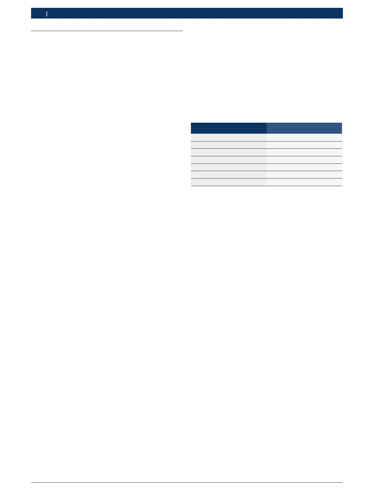
i The start of delivery for the corresponding cylinders
must occur at the following angles.
Type of pump Start of delivery
3-cylinder pumps every 120 degrees
4-cylinder pumps every 90 degrees
5-cylinder pumps every 72 degrees
6-cylinder pumps every 60 degrees
8-cylinder pumps every 45 degrees
10-cylinder pumps every 36 degrees
12-cylinder pumps every 30 degrees
i Deviation from the angles listed in the previous
table corresponds to the cam offset of the particular
cylinder.
i For certain fuel injection pump types (for e.g. ZWM
Stage II) the pre-stroke must be set on each cylinder.
12. After the fuel injection pump has been set, discon-
nect the test oil high pressure line and connect the
test oil return line.
 Loading...