1 689 988 262 2017-12-26| Robert Bosch GmbH
56 | EPS 625 | Initial start-upen
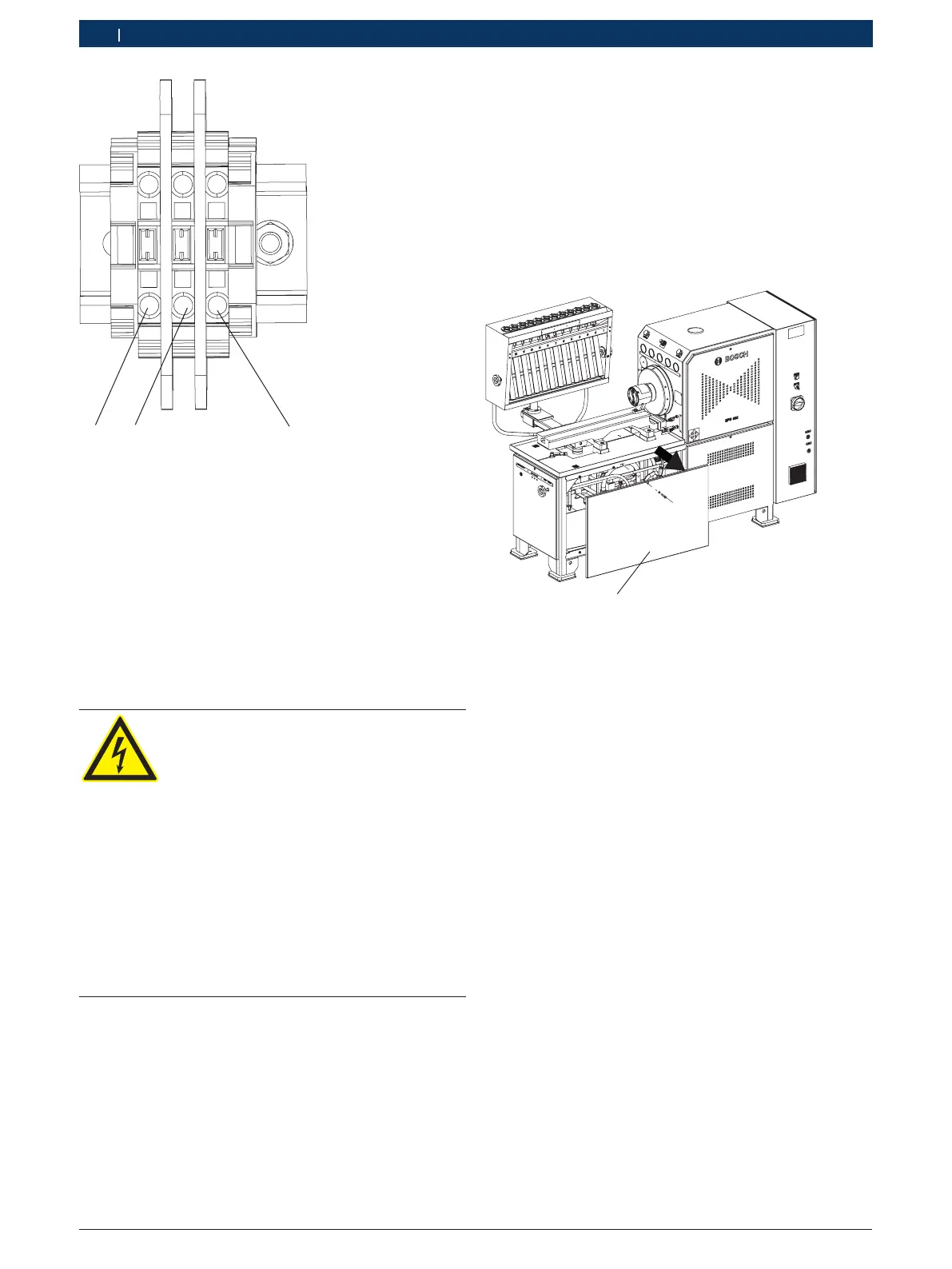
Fig. 19: Terminal block for additional 230 V AC power supply
1 Phase
2 Neutral conductor
3 Protective conductor
i Heed the circuit diagram
8. Connect the cable of the multiple socket outlet as
follows:
$ Phase to terminal 16
$ Neutral conductor to terminal 17
$ Protective conductor to terminal PE
Danger - Risk of electric shock from live
parts
Electric shocks resulting from contact
with live parts (e.g. master switch, print-
ed circuit boards) can cause injury, heart
failure and fatality.
¶ Work on electrical installations or
equipment is only to be performed by
qualified electricians or trained person-
nel under the guidance and supervision
of an electrician.
¶ Cover or cordon off live parts.
¶ Never touch live parts or parts with
damaged insulation.
9. Switch on the EPS 625.
10. Use a multimeter to check the voltage between the
phase and neutral conductor at the multiple socket
outlet.
The voltage should be 230 VAC 10%.
i The power supply must be checked if the voltage is
not 230 V AC +- 10 %. Check the protective conductor.
11. Position the multiple socket outlet in a safe location.
12. Close the switch cabinet.
"This completes connection of the additional power
supply.
4.4.4 Test oil connections
i All the test oil connections of the EPS 625 are con-
nected at the factory and are ready to use.
1. Open the bottom rear panel (Fig.20,Pos.1).
458868_85Nkv
1
Fig. 20: Opening the bottom rear panel
1 Bottom rear panel
2. Check if any hydraulic connections are disconnected.
i If there are any connections that have come loose,
restore the connections.
3. Loosen the fasteners (Fig.13,Pos.2) on the tank
cover.
4. Open the cover (Fig.13,Pos.1).
! Use only test oil ISO 4113. Do not use inflammatory
liquids such as petrol, naphtha or thinner.
5. Clean the test oil tank thoroughly with a clean soft
cloth.
 Loading...