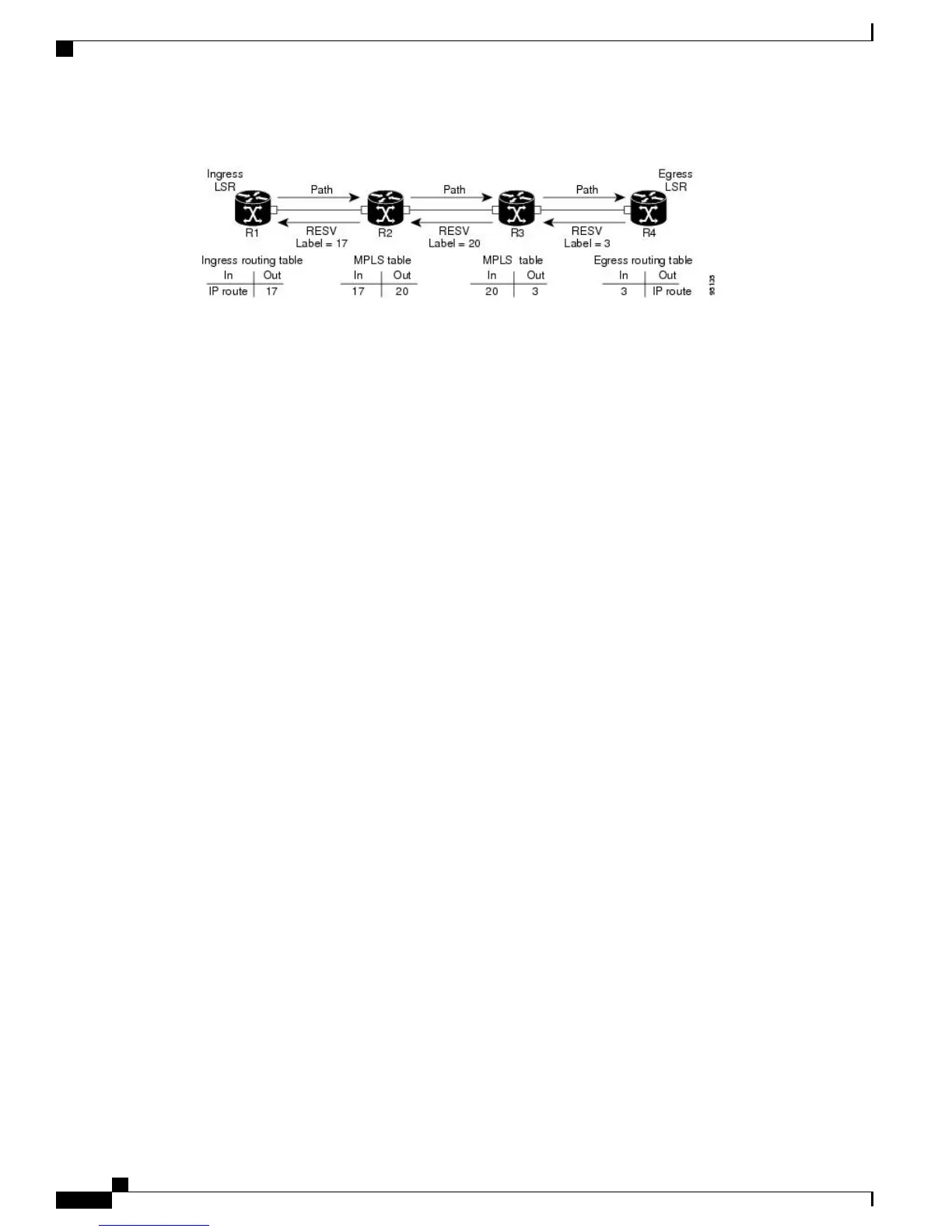
Figure 8: RSVP Operation
The Path messages reserve resources along the path to each node, creating Path soft states on each node. When
the tail node receives a path message, it sends a reservation (RESV) message with a label back to the previous
node. When the reservation message arrives at the previous node, it causes the reserved resources to be locked
and forwarding entries are programmed with the MPLS label sent from the tail-end node. A new MPLS label
is allocated and sent to the next node upstream.
When the reservation message reaches the head node, the label is programmed and the MPLS data starts to
flow along the path.
High Availability
RSVP is designed to ensure nonstop forwarding under the following constraints:
•
Ability to tolerate the failure of one or more MPLS/O-UNI processes.
•
Ability to tolerate the failure of one RP of a 1:1 redundant pair.
•
Hitless software upgrade.
The RSVP high availability (HA) design follows the constraints of the underlying architecture where processes
can fail without affecting the operation of other processes. A process failure of RSVP or any of its collaborators
does not cause any traffic loss or cause established LSPs to go down. When RSVP restarts, it recovers its
signaling states from its neighbors. No special configuration or manual intervention are required. You may
configure RSVP graceful restart, which offers a standard mechanism to recover RSVP state information from
neighbors after a failure.
Graceful Restart
RSVP graceful restart provides a control plane mechanism to ensure high availability (HA), which allows
detection and recovery from failure conditions while preserving nonstop forwarding services on the systems
running Cisco IOS XR software.
RSVP graceful restart provides a mechanism that minimizes the negative effects on MPLS traffic caused by
these types of faults:
•
Disruption of communication channels between two nodes when the communication channels are separate
from the data channels. This is called control channel failure.
•
Control plane of a node fails but the node preserves its data forwarding states. This is called node failure.
Cisco IOS XR MPLS Configuration Guide for the Cisco CRS Router, Release 5.1.x
114
Implementing RSVP for MPLS-TE and MPLS O-UNI
High Availability