This figure illustrates a control plane failure and shows the process and results of a control plane failure leading
to loss of connectivity.
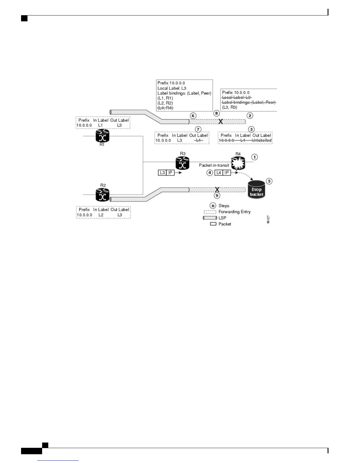
Figure 4: Control Plane Failure
1
The R4 LSR control plane restarts.
2
LIB is lost when the control plane restarts.
3
The forwarding states installed by the R4 LDP control plane are immediately deleted.
4
Any in-transit packets flowing from R3 to R4 (still labeled with L4) arrive at R4.
5
The MPLS forwarding plane at R4 performs a lookup on local label L4 which fails. Because of this failure,
the packet is dropped and NSF is not met.
6
The R3 LDP peer detects the failure of the control plane channel and deletes its label bindings from R4.
7
The R3 control plane stops using outgoing labels from R4 and deletes the corresponding forwarding state
(rewrites), which in turn causes forwarding disruption.
8
The established LSPs connected to R4 are terminated at R3, resulting in broken end-to-end LSPs from R1
to R4.
9
The established LSPs connected to R4 are terminated at R3, resulting in broken LSPs end-to-end from R2
to R4.
Phases in Graceful Restart
The graceful restart mechanism is divided into different phases:
Cisco IOS XR MPLS Configuration Guide for the Cisco CRS Router, Release 5.1.x
12
Implementing MPLS Label Distribution Protocol
LDP Graceful Restart