EasyManua.ls Logo

Cisco D9854 - Setting Admin User Privileges via a Telnet Connection

Cisco D9854
440 pages
To Next Page IconTo Next Page
To Previous Page IconTo Previous Page
Loading...
Chapter 3 Installation
36
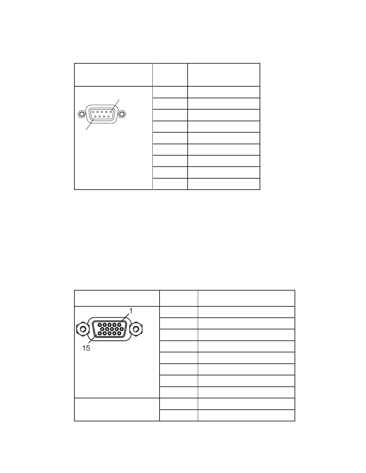
RS-232 Data Connector Pin Allocation
The table shows the RS-232 Data connector and the pin allocation:
Connector
Normally
closed pin
Common pin
1
9
1
Not connected
2
TxD
3
RxD
4
Not connected
5
Ground
6
Not connected
7
Not connected
8
Not connected
9
Not connected
Cue Tone/Cue Trigger Interface
The D9854/D9854-I receiver is equipped with a connector labeled Cue Tone/Relay
for alarm relay outputs for remote alarm signaling. This connector provides Cue
Tone, Cue Trigger and Alarm relay functionality. These outputs are user-
configurable via the Setup Menu on the front panel.
The connector is a 15-pin sub-D female connector. The following diagram shows the
connector and the pin allocation table for Cue Tone, Cue Trigger and Alarm relay
connections.
Connector
Pin
Pin allocation
1
Cue Trig 1
2
Cue Trig 2
3
Cue Trig 3
4
Cue Trig 4
5
Cue Trig 5
6
Cue Trig 6
7
Cue Trig 7
8
Cue Trig 8
9
Not connected
10
Alarm - Ground

Table of Contents

Other manuals for Cisco D9854

Related product manuals